

What is a DIN Rail Proto Board?
This is a board with multiple 35mm DIN rails attached for easy prototyping and design.
I have oftain read about folks using DIN rails inside cabinets to mount their CNC electronics. The problem I found was getting things laid out efficiently.
For this reason I designed the "DIN Rail Proto Board".
Since it has four rails spaced 2" apart, I have a ton of space to figure out how to efficiently layout my electronics.
Construction
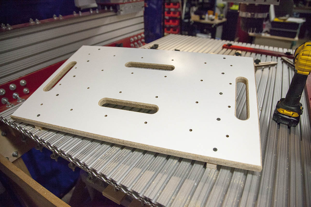
Main Board
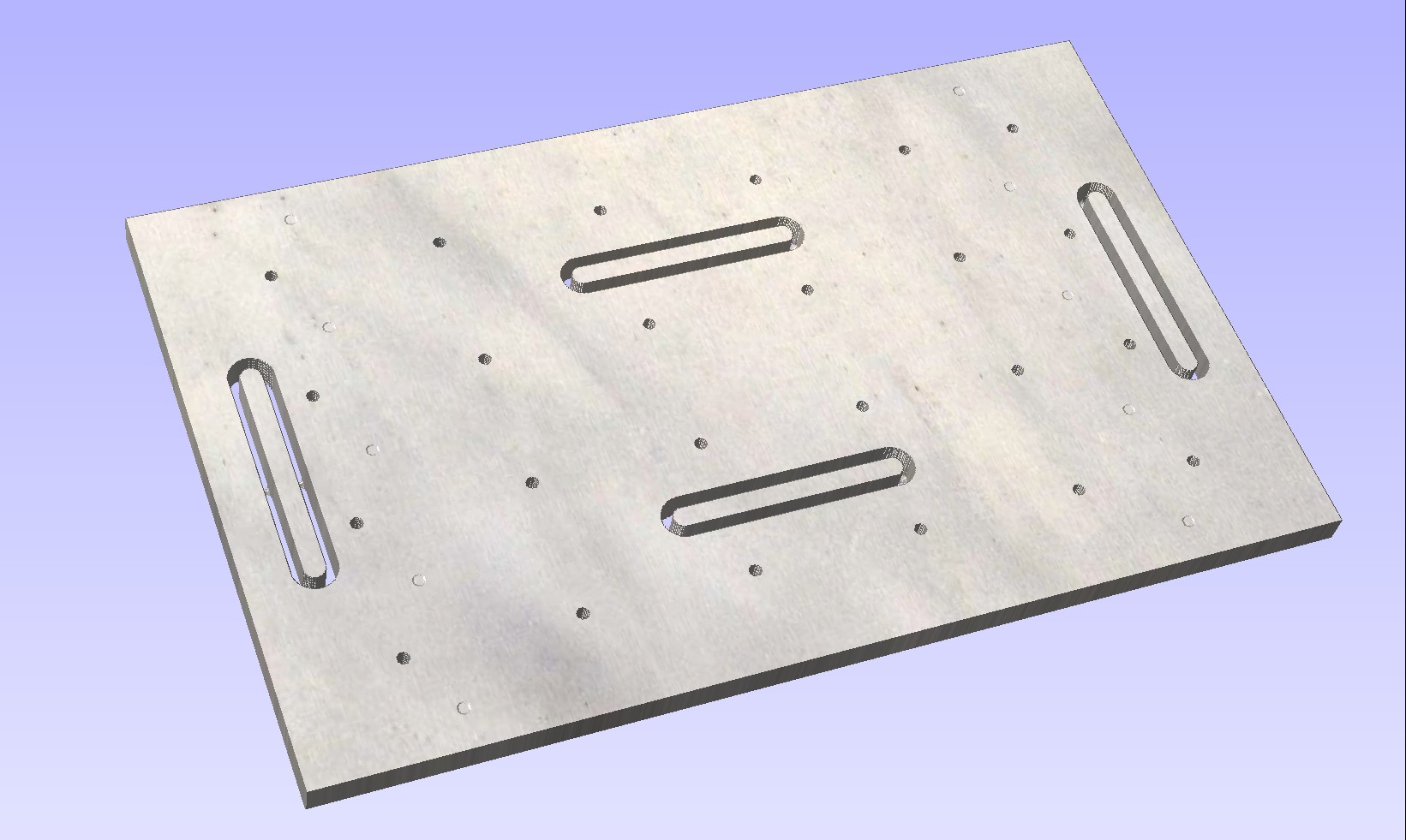
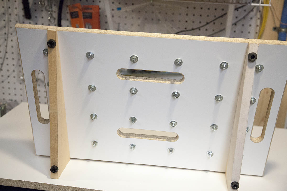
The main component on the proto board is the main board shown here.
It's a piece of 3/4" melamine coated particle board cut 24" x 14-3/4".
Four slots are cut into the board for routing wires. The two slots on the sides also serve as handles.
There are holes to mount the 35mm slotted din rail using 1/4" hardware.
I also make some shallow holes on each end to make the location for screws. These screws will be used to mount an angled piece of stock so that the board is angled.
You can get the drawing file here:
Din Rail Proto Board Drawing File
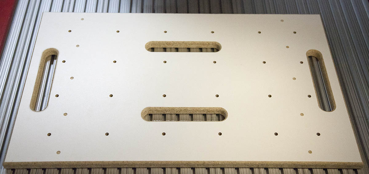
Version 3 of the DIN Rail Proto Board
After using the version 1 proto board I added the following changes.
- Added some extra slots to help with wire routing.
- Added a set of holes along the outer edge for some future upgrades.
You can get the drawing file here:
Legs
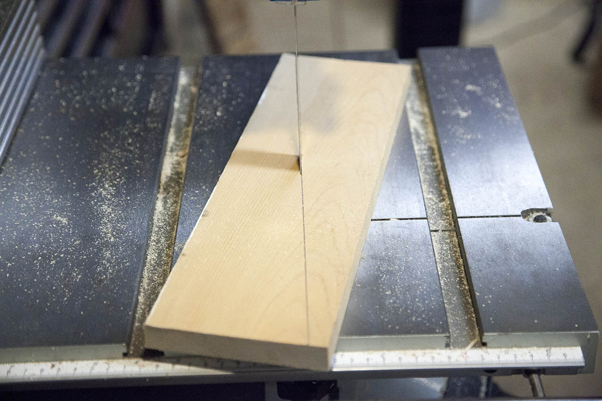
The legs are cut from a piece of 3/4" stock 14-1/2" x 4-1/2"
I recommend wood as particle board will split when you attach it to the main board.
I measure in on each corner 1/2" and mark. I then draw a line between the marks.
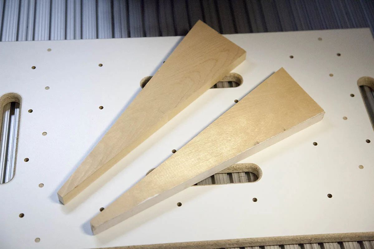
I then just cut on the line. This yields me the two legs shown here.
If you use a wider board you will get more tilt to your board.
Din Rail
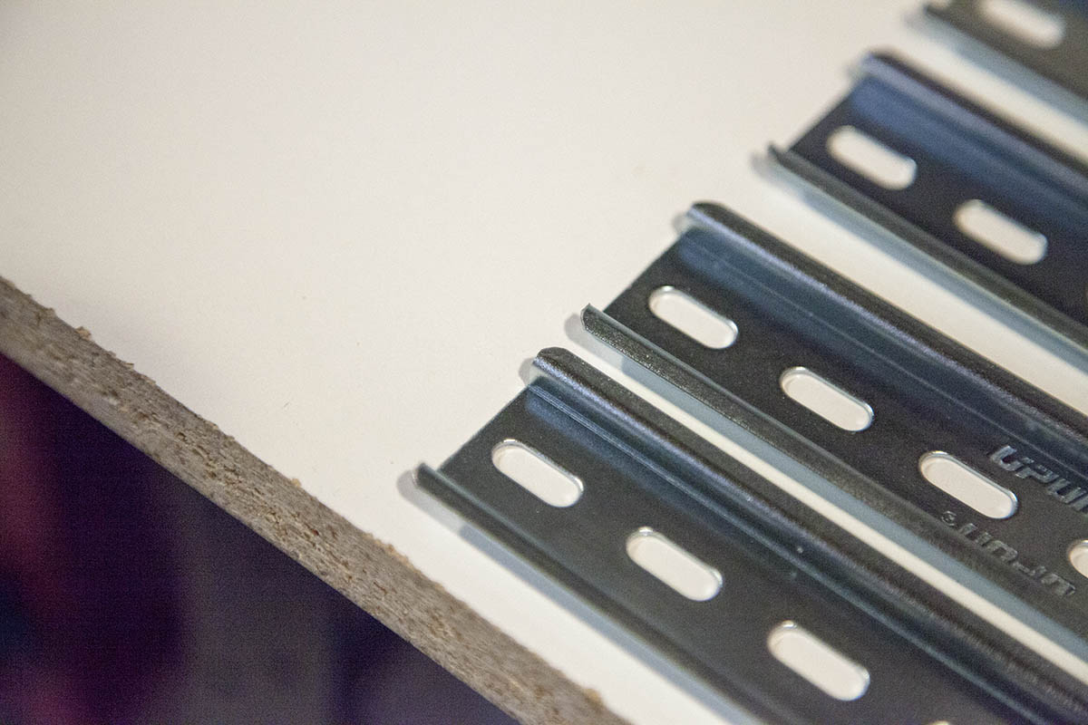

I recommend the following din rail:
Din Rail 10 Pieces 39-3/8" long
Cut two pieces exactly in the center, using a reciprocating saw, hack saw or Jig Saw.
This will yield you four pieces 19-5/8" long. Make sure you taper the edges and remove any burrs.
Assembly
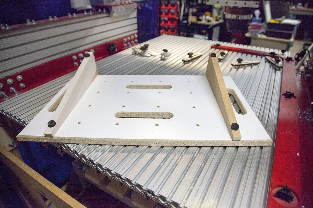
Attach Legs
The legs are attached by setting the main board on top of the legs.
Mate the cut portion of the leg against the bottom of the main board and center on the pilot marks. It will be a lot easier if you have a helper.
The front screw should only be about 1" - 1-1/4" long so that it does not go all the way through the leg. The remaining screws can be longer. I used 2" screws.
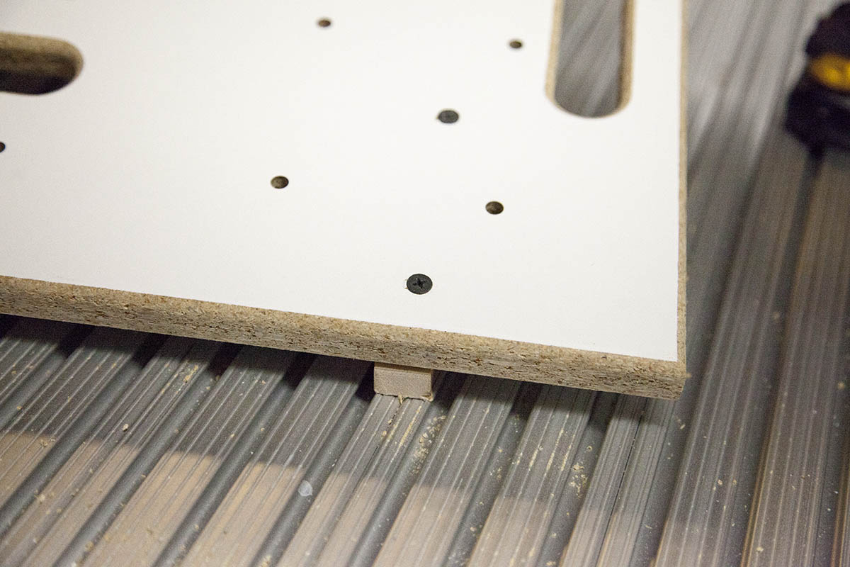
TIP:
Try clamping a 2x4 to the edge of a table as shown here:
This will keep the proto board from sliding off as you screw it in place.
Attach Feet
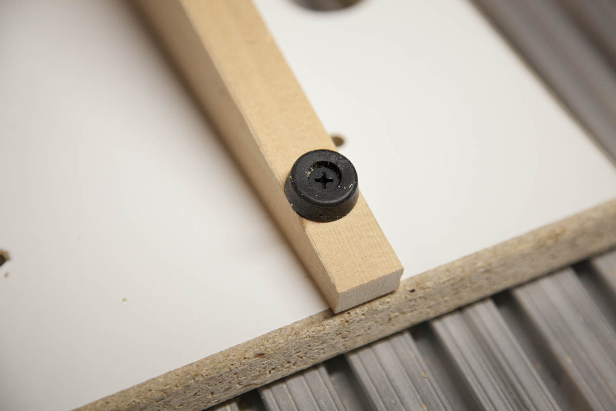
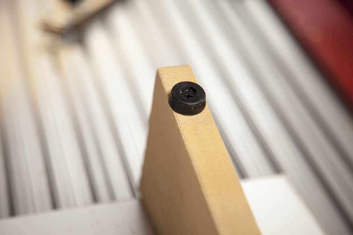
Add some small rubber feet to the bottom of the legs as shown here.
I attached each foot about 1" from the edge.
You can get the rubber feet here:
Attach Din Rail
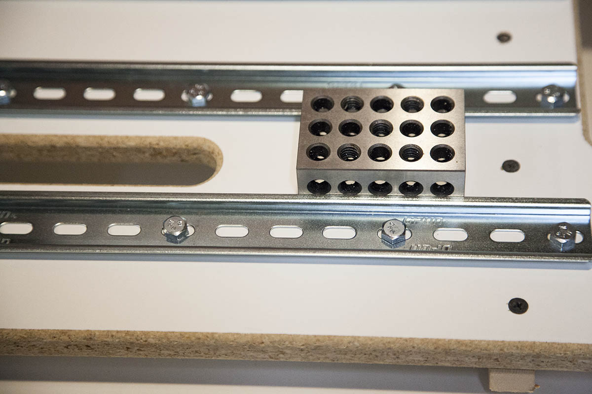
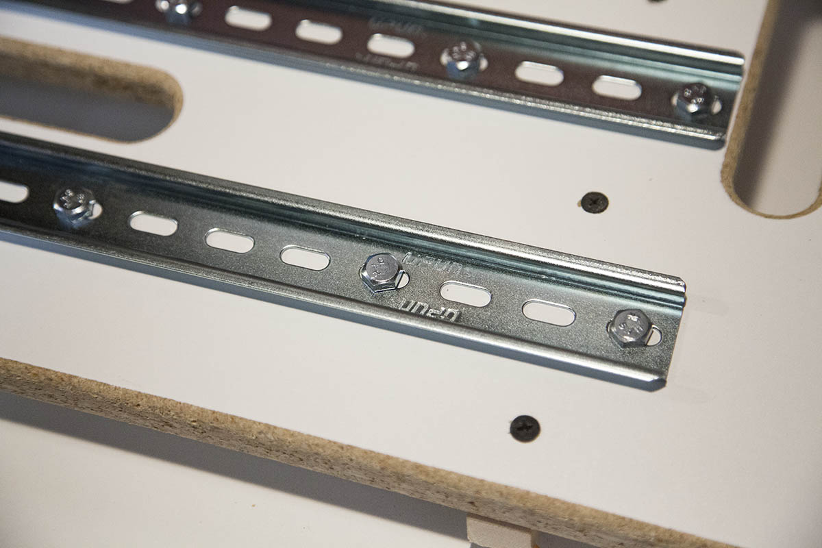
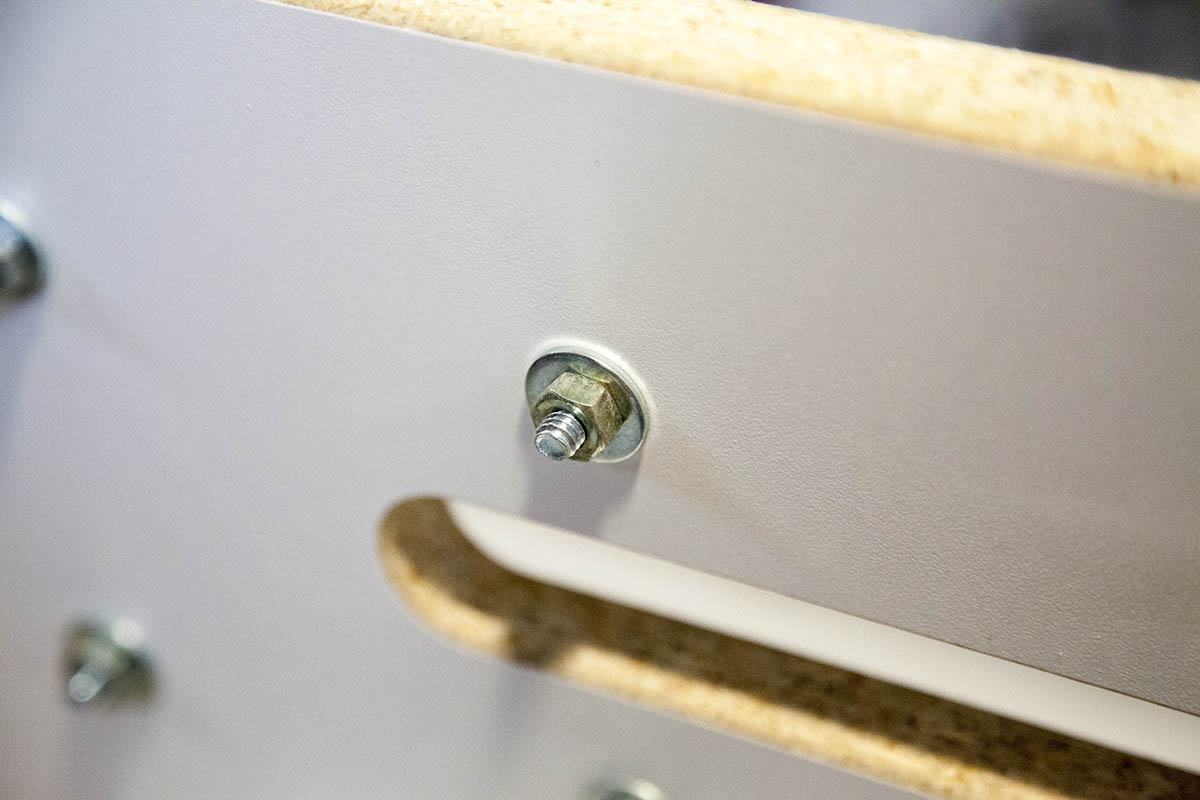
Place the din rail over the holes and slip some 1/4-20 x 1-1/4" bolts through the holes as shown here.
The bolts can be longer but they need to be full thread or they wont fit through the slots in the din rail.
Add a 1/4" washer and nut to secure.
I started on the bottom rail and used a 2" spacer to get the distance between the rails perfect. This will help if I want to design a large din rail mount that spans two or more rails.
All Done
That's all there is to it. The DIN rail proto board is complete.
Proto Board in Action
This is my first DIN rail design using my proto board. It has gone through several revisions and with a little more experimenting, I should be able to get a much more compact design.