

The HY02D223B Type 1 as I call it, is sometimes referred to as the genuine Huanyang Inverter. This inverter has a great deal of features and settings, as well as a Modbus interface.
You can purchase various genuine Huanyang inverters with ether 220V or 110V input. In addition either input type can drive 220V and 110V 3 Phase motors. It is just a matter of settings.
Note that you can drive a lower powered motor with a higher powered VFD. IE you can drive a 1.5KW with a 2.2KW spindle. Going the other way can be more difficult.
I ordered this VFD along with a 2.2Kw spindle from Amazon here:
Air Cooled 2.2Kw Spindle and VFD
Water Cooled 2.2Kw Spindle and VFD
You can also get one without the spindle here:
Power the VFD
We need to get some power to your VFD so that you can edit some of the parameters.
Power Cord


To start you will need to make a power cord. Since you will also need a cord for your spindle, it's best to purchase a 50' 14guage extension cord and cut the ends off.
Cut the cord in half and use one half to make your VFD power cord and the other to make your spindle cord.
You will need a power plug to match your shop power outlets.
You can pickup an extension cord here:
Connect Cord to VFD
This controller can be powered by three phase or single phase. To connect to a 220v single phase you connect the other end of the power cord to the terminals shown here.
Black and white leads connect to R and T terminals. Green is connected to the ground shown here.
Plug-in the Power Cord
Re-check your connections, then plug the power cord into the 220v outlet.
After a second or two you should see your VFD come to life. Once the unit boots, you will be presented with a display that looks something like this. Don't be concerned about the actual display contents at this point as it may differ from mine.
Setting Parameters
Before moving forward, you need to make sure some of the parameters are setup properly before connecting the spindle. Failure to do so could burn up your spindle.
How to edit a parameter
To edit one or more parameters, start by hitting the PRGM button. You will be presented with a Pdxxx display like the one shown here.
You change the actual parameter number you want to edit by using the up/down arrows. Here I changed the parameter number to Pd004.
Note that you can use the SHIFT button to move the digit you will be affecting with the arrow keys.
To edit a parameter hit the SET button. You will be presented with the value of the parameter you selected. In this case, parameter Pd004 has a value of 400.00 as shown here.
To change the value, use the up/down arrows. Remember you can use the SHIFT button to change the digit you want to edit.
To apply the new value, hit the SET button again. The new value will be saved and you will be taken to the next parameter. In this case, we moved to parameter Pd005.
Initial Parameters
Change the following parameters before proceeding.
Motor Frequency (Set in this order)
Pd005=400
Pd004=400
Pd003=400
Pd072=400
Note that you have to set Pd005 first in order to set Pd003 and Pd004.
If you are driving industrial 3 Phase motors you will have to set these values to 50 or 60Hz. Note that in most cases you can drive these motors at up to twice their rated frequency. For example I have a 60Hz 1725 motor and I can drive it up to 120Hz for an RPM of almost 3600 RPM, and all the way down to 300 RPM reliably.
Motor Settings for 220V Motors
PD0011=220 (Max Voltage)
PD0141=220 (Rated Motor Voltage)
PD0142=8.5 (Rated Motor Current)
PD0143=4 (No of Polls)
PD0144=3000
Motor Ratings for 110V Motor
PD0011=110 (Max Voltage)
PD0141=110 (Rated Motor Voltage)
PD0142=8 (Rated Motor Current)
PD0143=2 (No of Polls)
PD0144=3000
Connecting the Spindle
Take the other half of the power cord and strip the insulation from both ends as shown here.
Disassemble the connector that came with the spindle and slip the sleeve over the cable as shown.
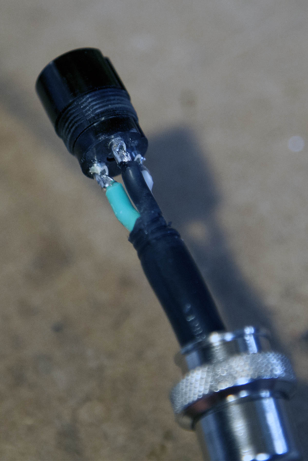

If the spindle has a four pin interface, solder the three wires to pins 1,2, and 3.
If the spindle has a 3 three pin interface, solder the three wires to each of the pins.
If your spindle has 4 pins, ignore pin 4 as it is spindle ground and wont be used.
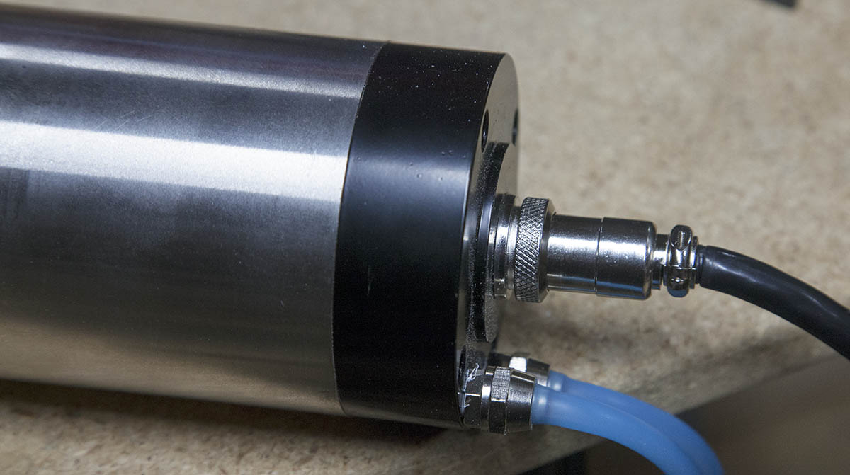
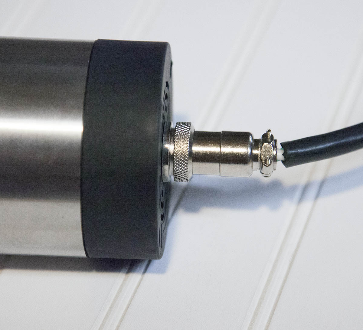
Re-assemble the connector and attach to the spindle as shown here.
Attach the other end of the cable to the terminals marked U, V, and W as shown here.
First Test
Press the SHIFT button until the Hz LED is displayed. Note that there are two Hz displays. The fist is the current running speed. The second is the target frequency.
Use the arrow buttons to set the frequency to 100 as shown here.
Press the run button and the spindle should spin up.
Note the direction that the spindle is turning. Facing the front of the spindle, it should be turning clockwise. If it is not you will need to reverse two of the spindle power leads.
How Does the Frequency Affect Spindle Speed
The VFD can be set to a frequency of 0 to 400Hz. The frequency directly affects the RPM of the spindle. Most of the spindles have a top speed of 24000RPM. If you set the frequency to 200Hz the spindle will turn at 12000RPM. Set to 400Hz the spindle will run at 24000RPM.
This VFD does not have a RPM reference feature, but can display the current running RPMS by moving the display to ROT.
Connecting a Potentiometer to the VFD
When all is said and done, you probably wont be using the potentiometer on your VFD once you can control the speed with Mach3. I feel this is an important step, It will ease the transition to full automation.
You will need a 5 or 10K potentiometer, you can pick one here:
Attach three wires to the POT, as shown here.
Connect the wire connected to the center lug on the POT, to the terminal labeled VI on the VFD.
Connect a wire connected to an end lug on the POT to the terminal labeled ACM on the VFD.
Connect the remaining lead from on the POT to the terminal labeled 10V on the VFD.
Setting VFD Parameters for a Potentiometer.
In order for the potentiometer to work, you need to make the following parameter changes.
PD070=0 (10v)
PD002=1 (analog pot)
Testing the Potentiometer
While set on the Hz display, rotate the potentiometer until the display reads F120.00, as shown here.
If the value reads 00.00 and will not change, your display is set on the running frequency, not the target frequency.
Hit the SHIFT button to set the display to target frequency, then make your adjustments.
To start the spindle, hit the RUN button. You can adjust the speed while the spindle is running. Once the spindle is running, you view the running frequency if you choose to.
This VFD does not have the ability to use actual motor RPMS to set the target frequency, but does have the ability to display the running RPMs.
Use the SHIFT key to select the ROTT display, as shown here.
While the spindle is running this display will show the actual speed of the spindle.
Again, you can make changes to the speed while the spindle is running. This is a good way to set your speed before starting a job.
Starting and Stopping the VFD with Mach3
In order to turn the spindle on and off, you need to setup and output on your controller. Some controllers have a built-in output relay that can be used.
In my case I am using a GeckoDrive G540 controller. It has two outputs called Output1 and Output2. These can be used to drive a relay that can control things. The G540 can drive the VFD directly by connecting GND and Output1 to the VFD.
Connect the GND lead (G540 GND) to the DCM position on the terminal block shown here (green wire).
Connect the Output lead (G540 Output1) to the FOR position on the terminal block (white wire).
Note that you will need to configure Mach3 in both the spindle section and the output pins to point to Output 1 on the G540.
See below for some configuration screenshots.
Setting VFD Parameters for Remote Start
In order for Mach3 to turn the spindle on and off, you need to make the following parameter changes.
PD001=1 (External terminal)
Testing the External Trigger
By clicking the spindle control button on the main Mach3 screen, you can toggle the spindle on and off.
Controlling Spindle Speed with Mach3
Using Mach3 to control the spindle speed using this VFD is very easy. You will replace the potentiometer with three leads from the G540.
Wiring
Connect three wires to the G540 as shown here:
In this case:
Black = VFD Ground (G540 Pos 7)
Yellow = VFD Output (G540 Pos 8)
Red = VFD +10VDC (G540 Pos 9)
Attach the red lead (VFD +10vdc) to the 10V position on the terminal block as shown here.
Important - I have found that on the 10V reference does not work on some of my VFDs. For this reason I used the 5V position.
If you use the 5V reference you have to change PD070 parameter to 5V.
PD070=1 (5v)
Attach the black lead (VFD Ground) to the ACM out position on the terminal block as shown here.
Attach the yellow lead (VFD Output) to the VI position on the terminal block as shown here.
Mach3 Configuration
You will need to make the configuration changes shown here in order for Mach3 to change the speed of the spindle.
Note that these are for a G540 connected to the VFD.
Use the pulley settings to dial-in the PWM signal sent to the VFD.
As stated before, I will be going into more detail in the actual workbook, but these settings should get you started.
Testing Mach3 Spindle Speed Control
By clicking the spindle control button on the main Mach3 screen, you can toggle the spindle on and off.
You can change the spindle speed by using the up and down arrows on the Spindle Speed Pane shown here.
You can also type the speed directly into the Spindle Speed field.
The VFD will display the spindle speed within a few RPMs as shown here.
Make sure you are on the ROTT display. If not, use the SHIFT button to change the current display mode.
If you cant get your Mach3 speed to match the speed shown on the VFD ROT display, try deleting the file called linearity.dat in the Mach3/macros/KRMx02 directory. When you restart Mach3, it will create a new linearity.dat file with a 1 to 1 speed curve.
Breaking Resistor
Please note that this VFD does not support a breaking resistor. While the manual indicates that it does, and even includes registers for setting it up. There is no circuitry to support it.
If for some reason you need a breaking resistor, you will need to look for another VFD.
That said, the VFD can control the spindle ramp up and down speed within its amperage load limits. I can can go from 24,000 RPM to 0 RPM in less than a second with small to medium bits. Large fly cutters will need a little more time to slow down.
MACH3 Speed Control Update
09/15/2018
I recently purchased a 110V 1.5KW Air cooled spindle with VFD. It came with a HY01D511B VFD.
This VFD is wired exactly the same as the HY02D223B and uses the same parameters. And while I did have to change the spindle output voltages from 220 to 110(for my square 110V spindle), everything else is identical.
The one exception is that this VFD came with a built-in speed control knob.
In order to control the speed externally via the G540, I had to change the jumper from the VR pins to the VI pins shown here.
Another problem I had was that for some reason the internal reference did not work correctly. I could only guess that this had to do with the wiring on the built-in potentiometer.
To fix this I used the 5V reference instead of the 10V wired to the G540. I also set the PD070 parameter to 5V.
PD070=1 (5v)
After I made the changes it worked perfectly.
Note that I have also purchased a 110V 2.2Kw VFD, it is identical to the one above but with more power. You probably wont get the full 2.2KW output power on 110V but I have never pushed a 2.2KW spindle to its full output.
Here is a 110V 2.2Kw VFD controlling 220V 1.5HP 3 phase motor. This type motor is 0-50Hz. And is what most VFDs are configured to work with by default.
Note that I set my max freq to 100Hz. This allows me to run the motor at higher speeds if needed.