

In this series, I will cover some of the CNC plasma cutter experiments I will be performing for future book research. Feel free to follow along, some of the information here may help you with your own plasma project.
The Machine

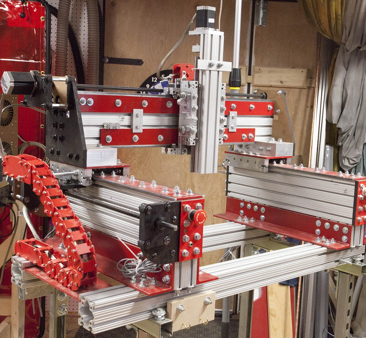
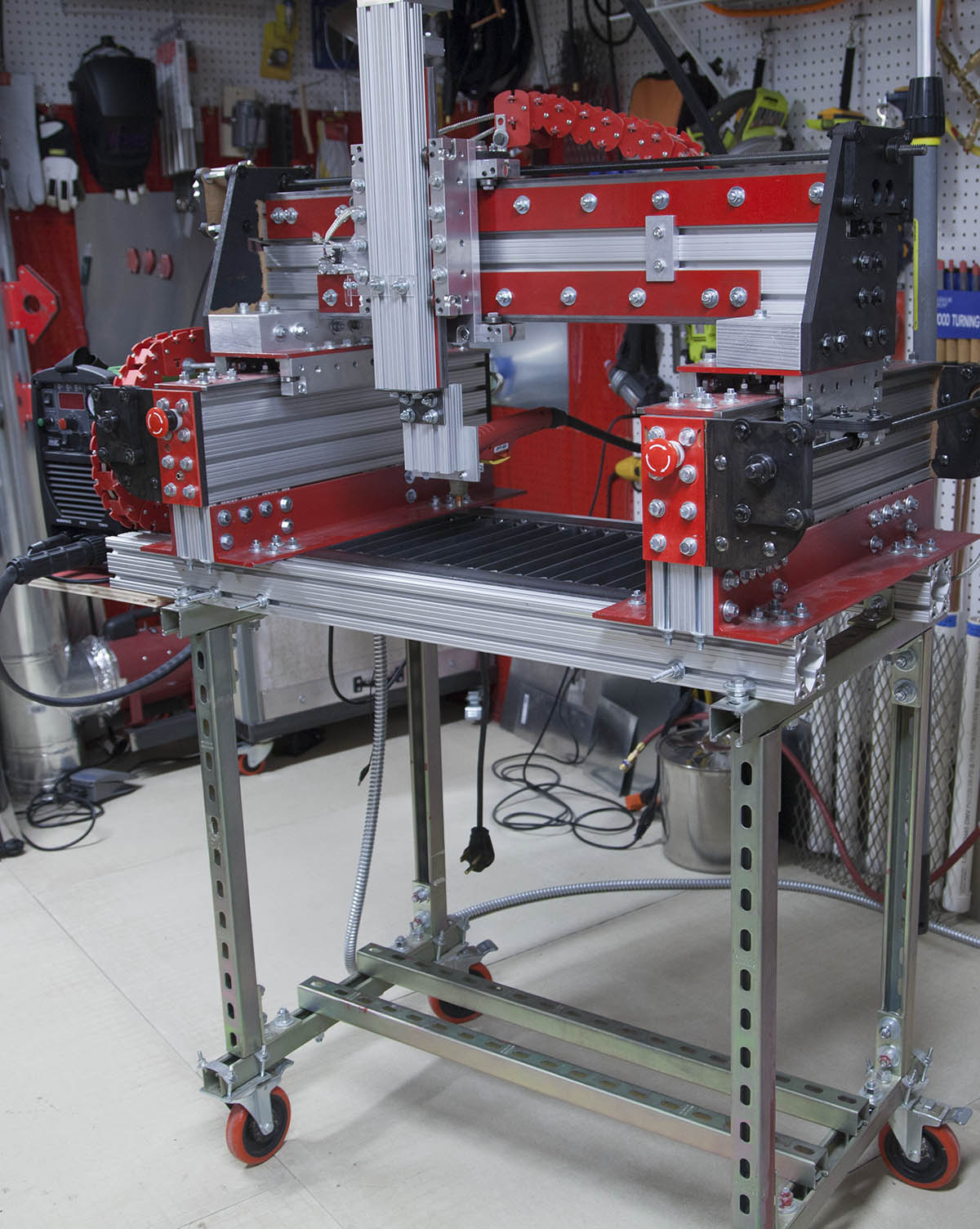
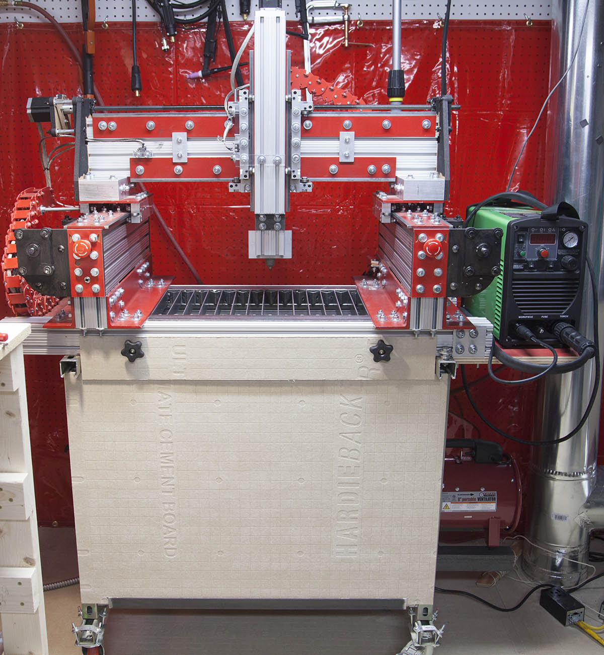
For these experiments, I will using my 18x14 KRMx02 build, shown here. This is one of the five build sizes you can build with my KRMx02 workbook.
This size was originally added to the others for use as a demo or in a school or home where space is a major concern. It has an 18" x 14" cutting area and is every bit as rigid and powerful as its bigger bothers.
This particular version has a steel stand with double locking rubber casters. To help brace the stand baltic birch plywood was added to protect the computer and dust collection system.
Why did I choose this build size? First, its small, I can move it around my shop with ease. Second the table can be removed as a single piece.
Keep in mind the goal is not to create a production CNC plasma cutter. Its to experiment with various aspects of CNC plasma cutting. It also means construction of the table will be minimal. It's a lot easyer (and cheaper) to redesign an 18" x 11" table than it is a 48" x 48" table if needed.
My findings will help me make decisions on a larger system designs later.
Not Quite Stock

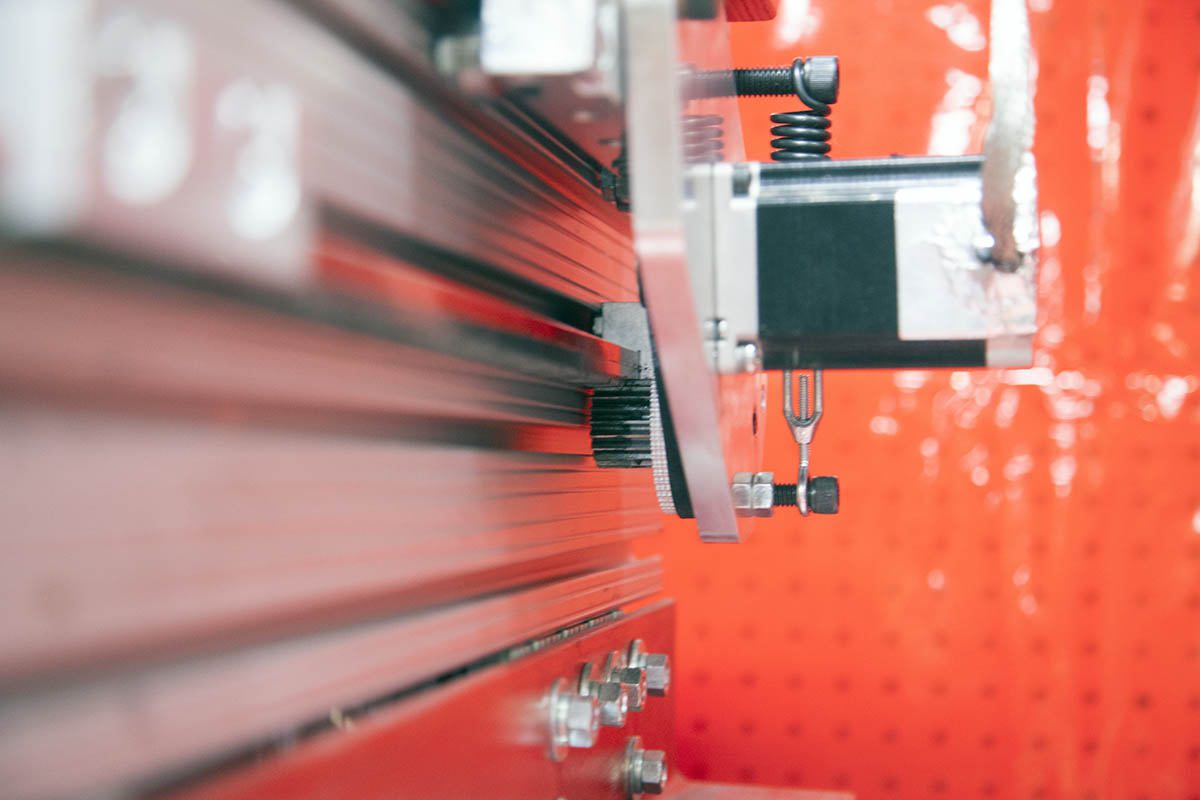
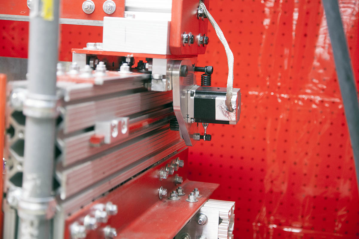
Just to start things off here. This machine is not quite a stock KRMx02. In an earlier experiment, I had removed the rack and pinion drives and replaced them with 1/2" five start ACME screws shown here.
Those experiments were to compare the accuracy of the ACME screws with the rack and pinion drives.
As part of the plasma experiments I removed every thing below the table. The router and its support electronics have also been removed.
First Things First
The first thing I did was to remove the table. The actual plasma table will be inserted between the two cross beams.
This will yield me a little over an 18" x 11" plasma cutting area. Not sure this is the smallest plasma cutter, but it will work for my initial R&D.
Wiring
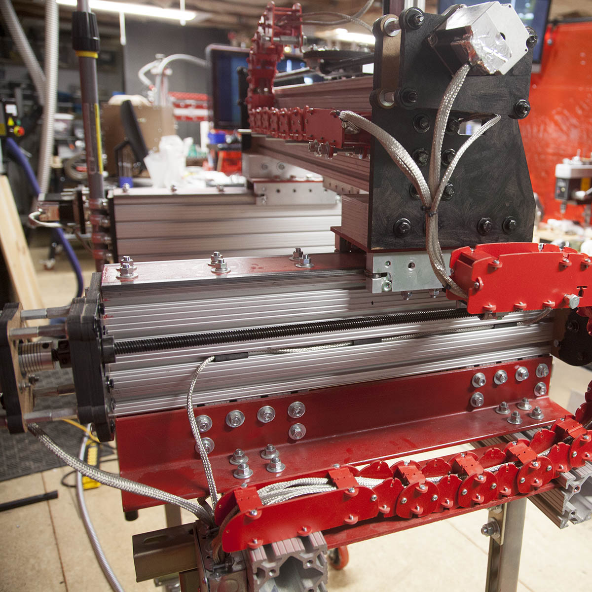
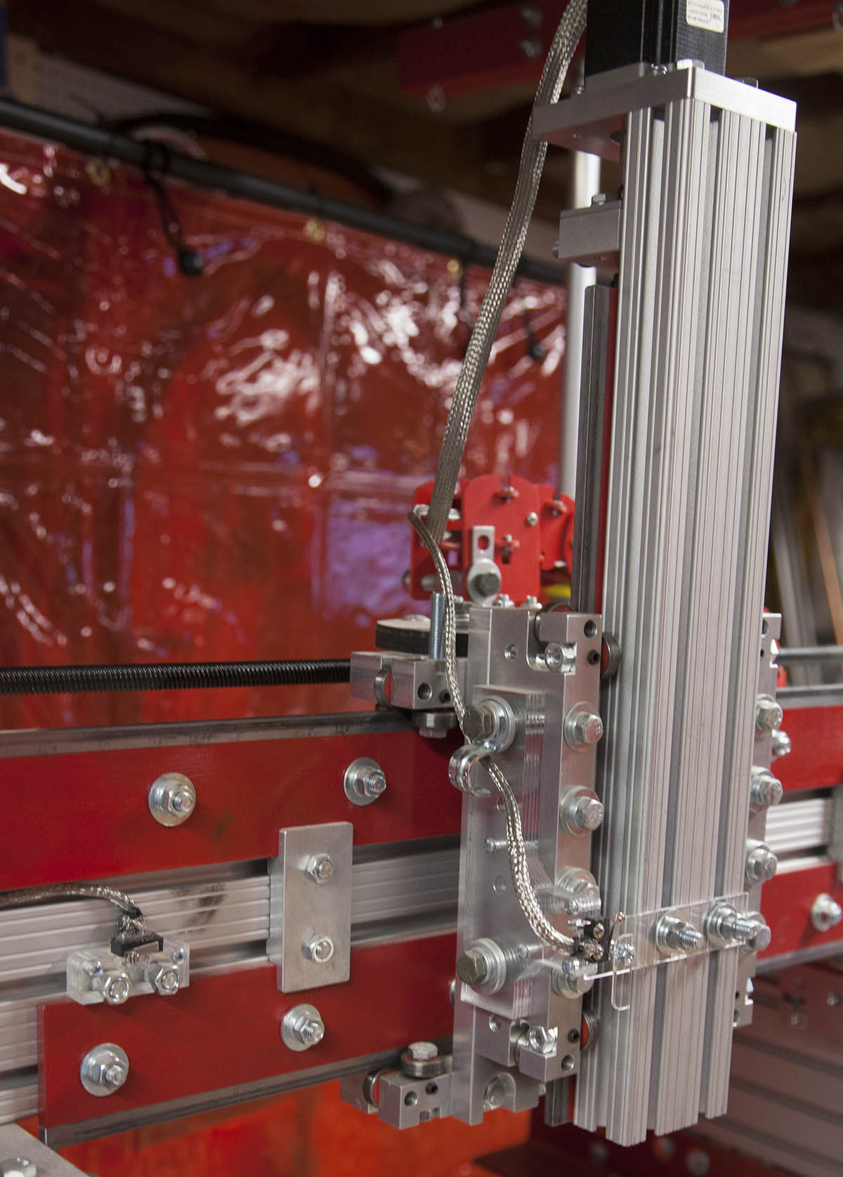
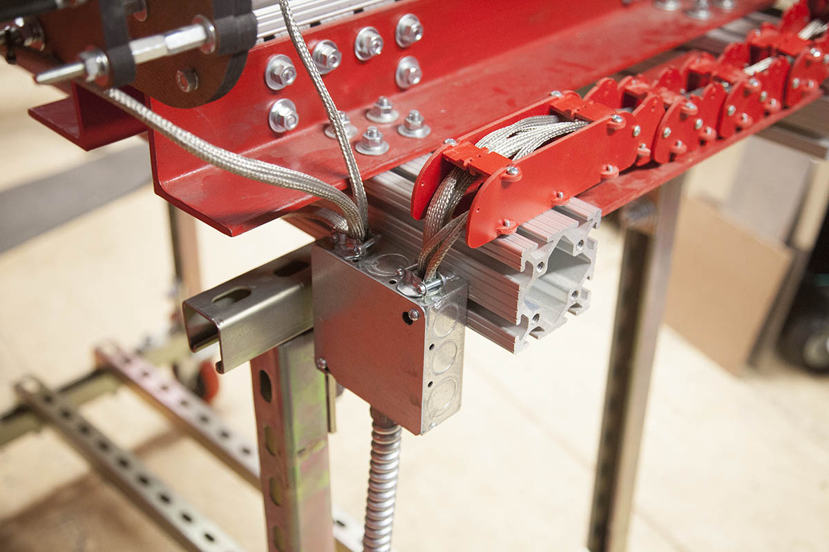
Next, I removed all the switch wiring and added shielded sleeves. In addition I cut the stepper motor cables and soldered my own 4 conductor (shielded) cable. I then added the shielded sleeves.
All the cables came together in a metal junction box. From there it traveled to a computer through a 25' metal conduit.
I'm not sure all this was necessary since most of the higher quality plasma cutters use a newer blowback pilot arc technology instead of the older HF pilot arc.
It did come in handy though as I did some CNC TIG welding experiments. My TIG welder has HF start and before I added the shielded cables the controller would get false Estop signals. Even using the Ethernet SmoothStepper it was too unreliable. The shielded cables and sleaves solved all these problems.
Other than the shielding the wiring is identical to that of the stock KRMx02.
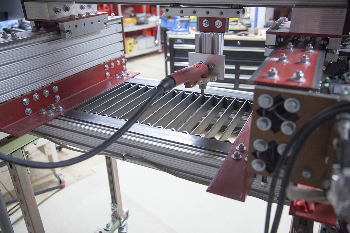
Torch Mount
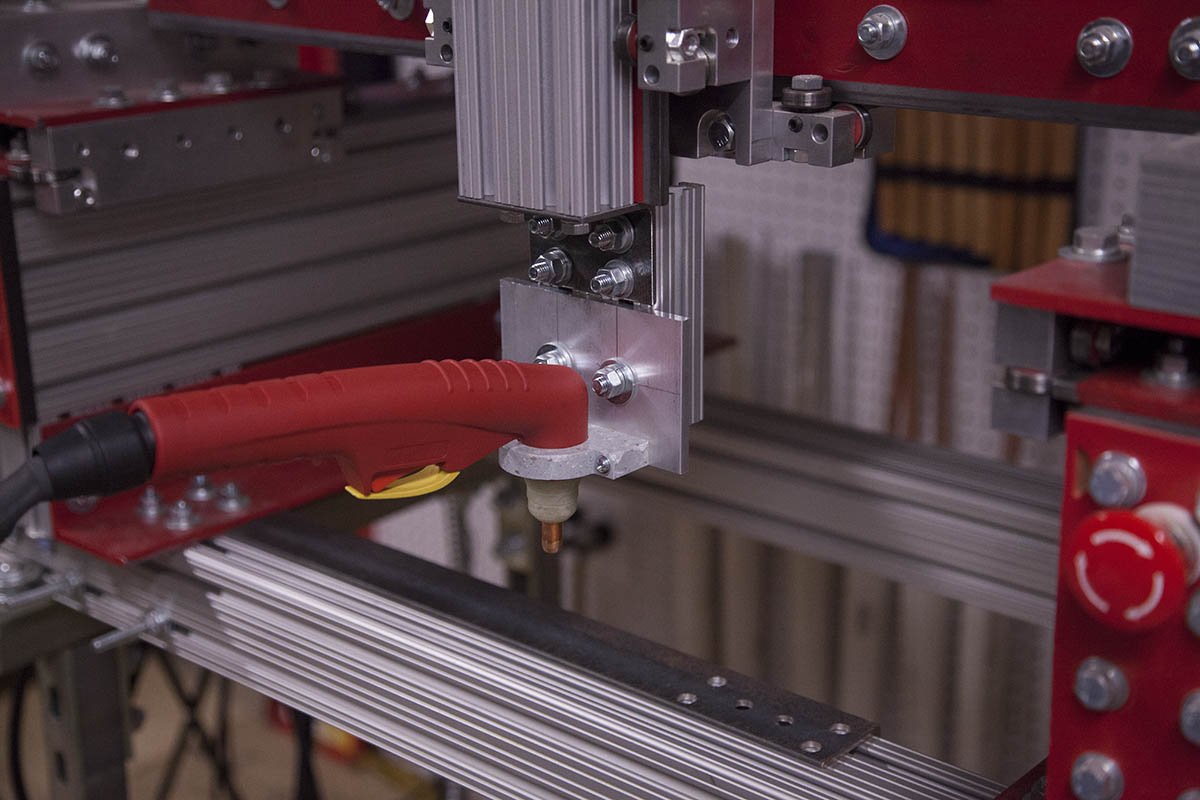
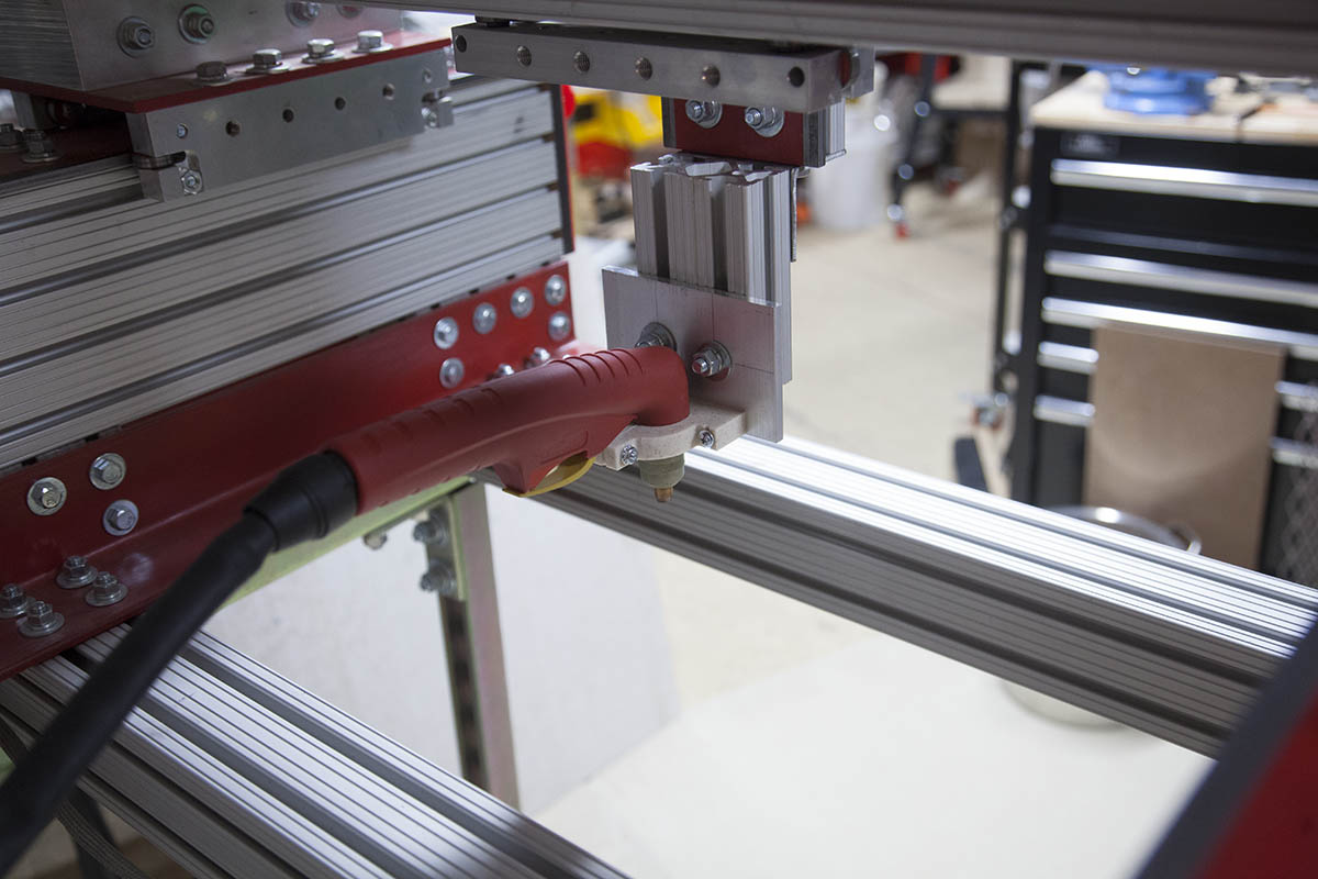

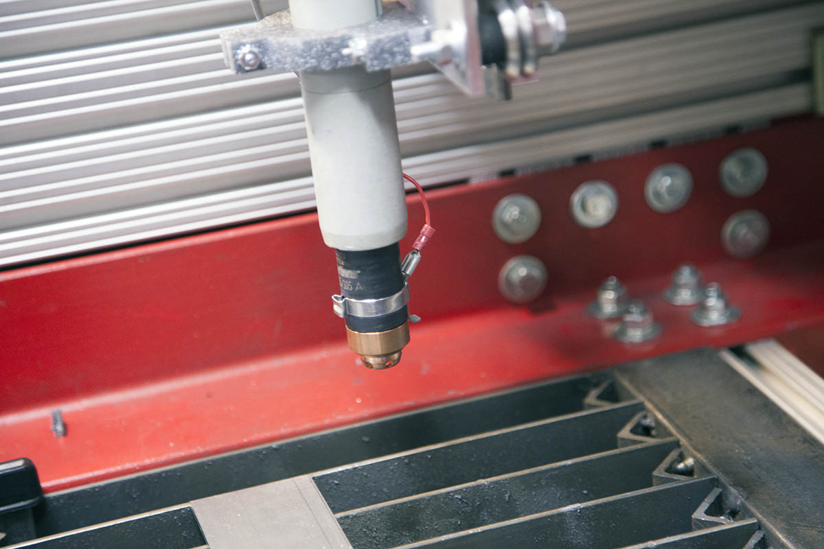
For the torch mount, I added a small piece of 3020 using a piece of angle iron shown here. This allowed me to lower the torch to a more useful height. Since it has T-slots, it can be raised or lowered if I need more height.
I then moved the torch to the rear of the machine. This makes it much easier access the torch tip and to set the initial height of the torch with Mach3.
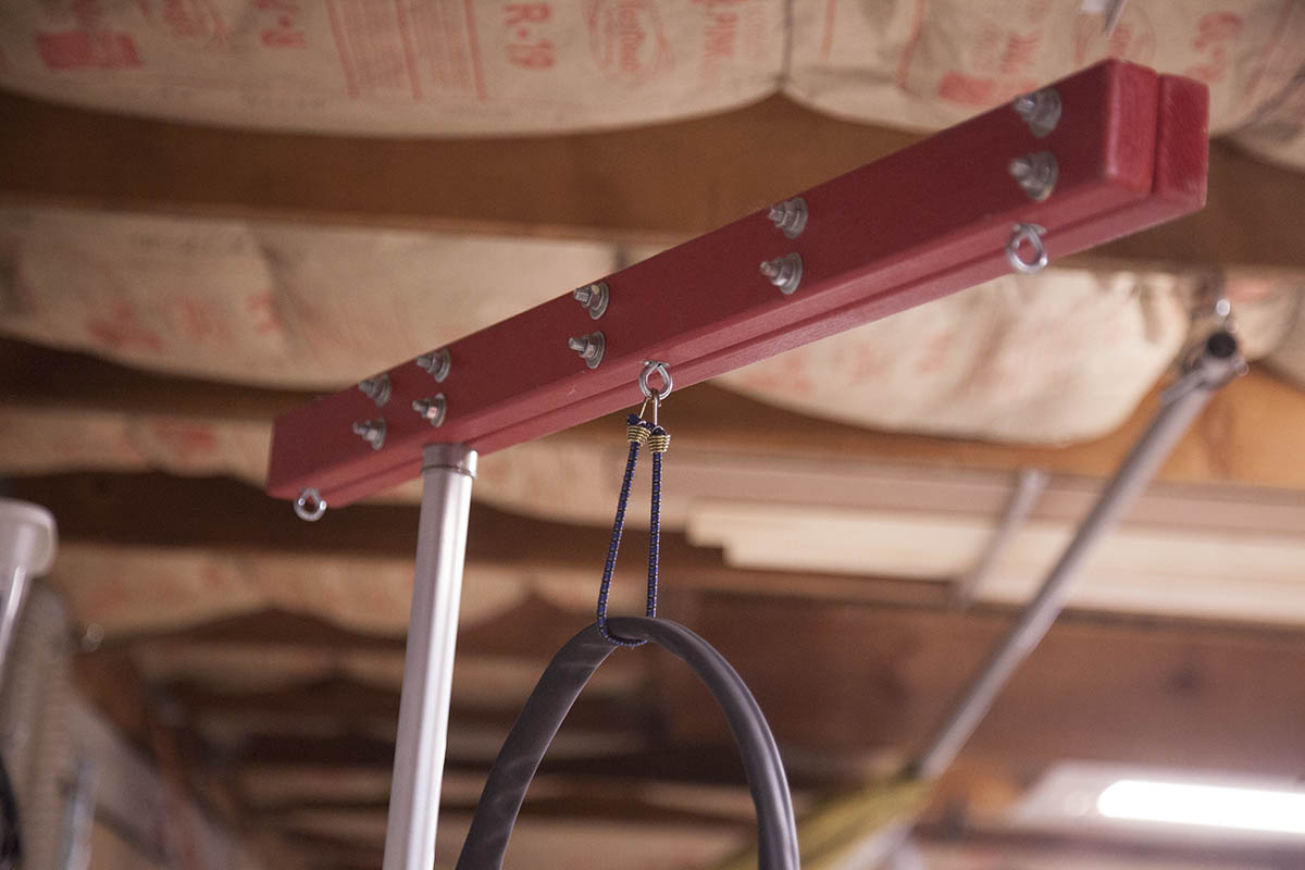
I use booms on all my KRMx02 builds to help support the vacuum hoses. They work equally as well holding the torch cable.
Plasma Table Insert
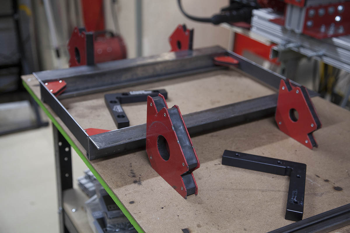
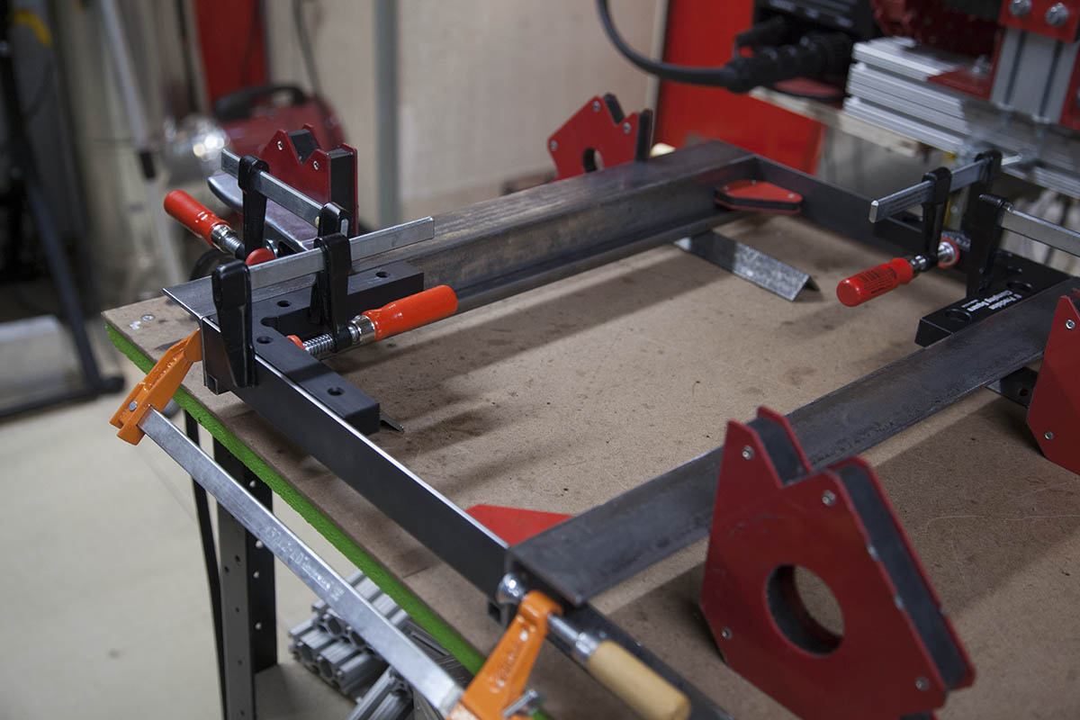
With the torch installed it was time to design the plasma table insert.
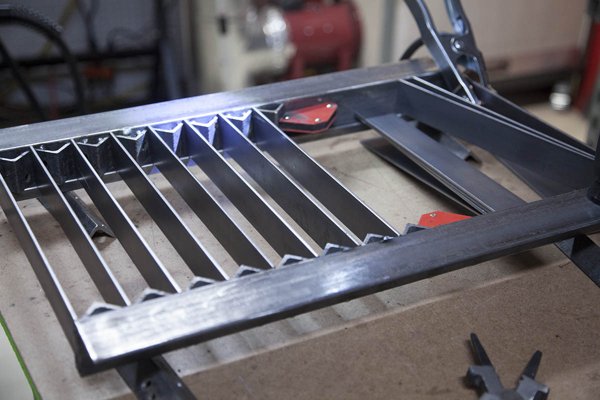
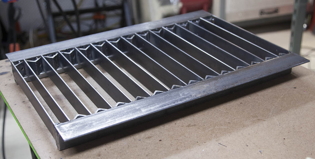
Its simple 2" angle with 1-1/2" flat bar stock wedged between some smaller 1" angle on end for easy replacement.
My Goto Welder

How did I create the plasma table insert? I used my trusty Everlast 251Si. This is a Synergic MIG welder that let me create the table in less than 2 hours.
The only real cleanup I did to the metal, was to wipe it down with acetone to remove any oil.
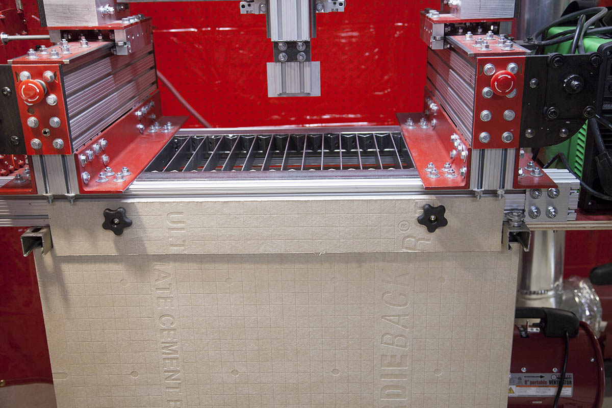
Add the Insert
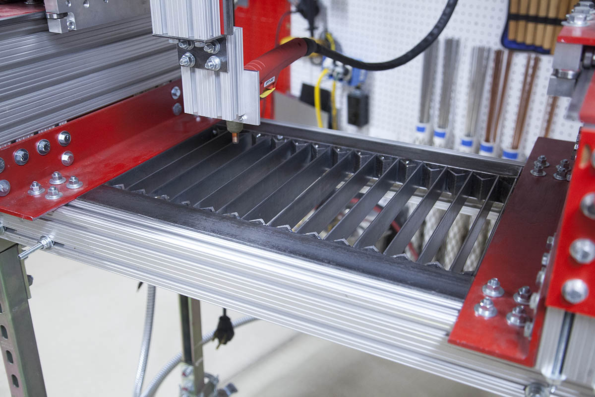
The insert is desinged to just drop into place between the two KRMx02 Cross beams shown here.
The weight of the insert is enough to hold it in place for now. Eventually I will probably add some sort of bracket to secure it better.
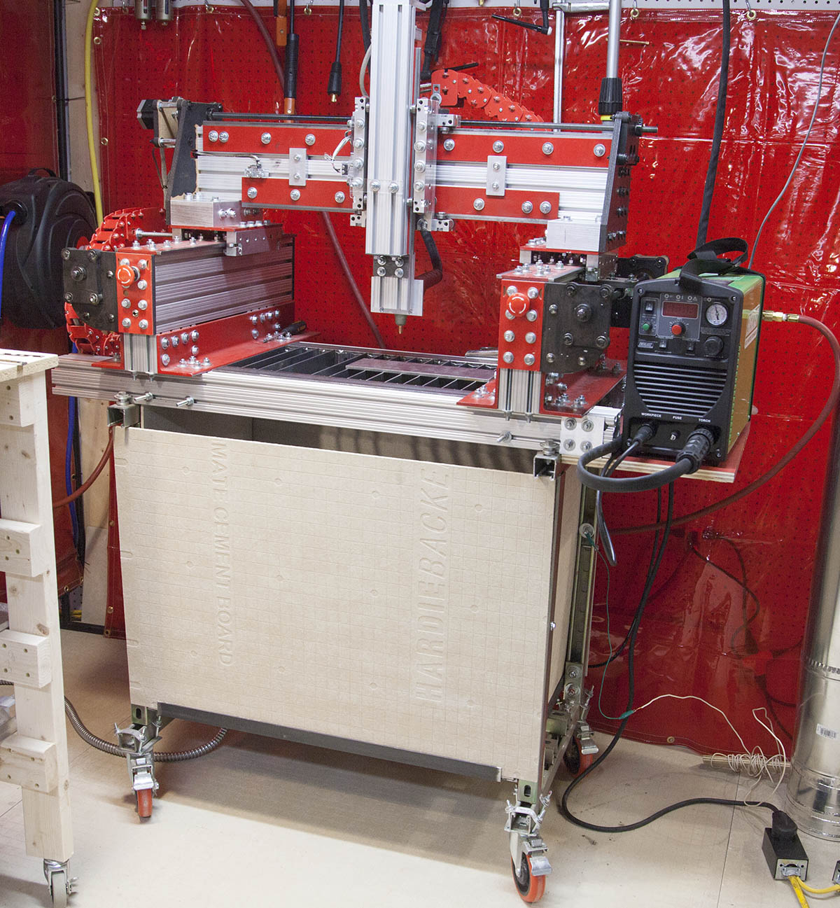
Computer Interface
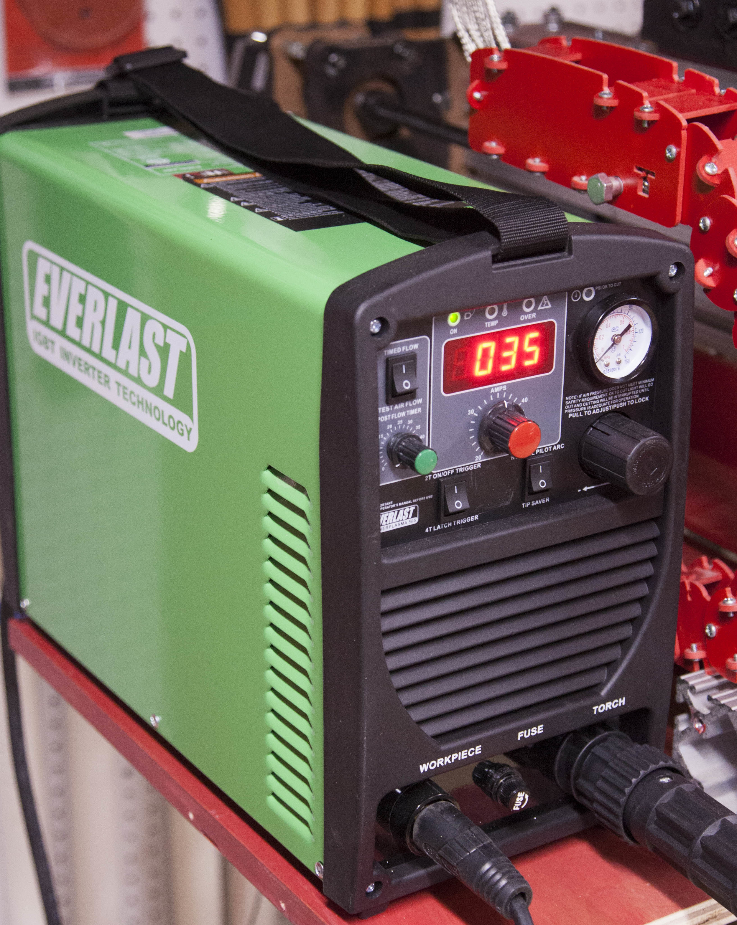
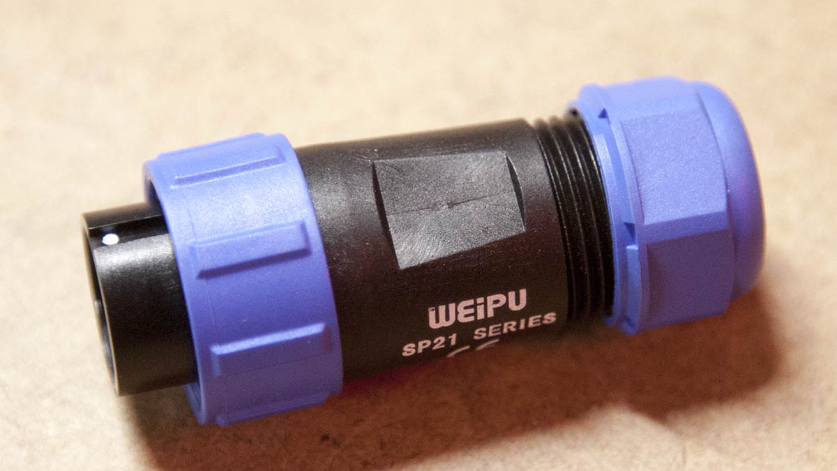
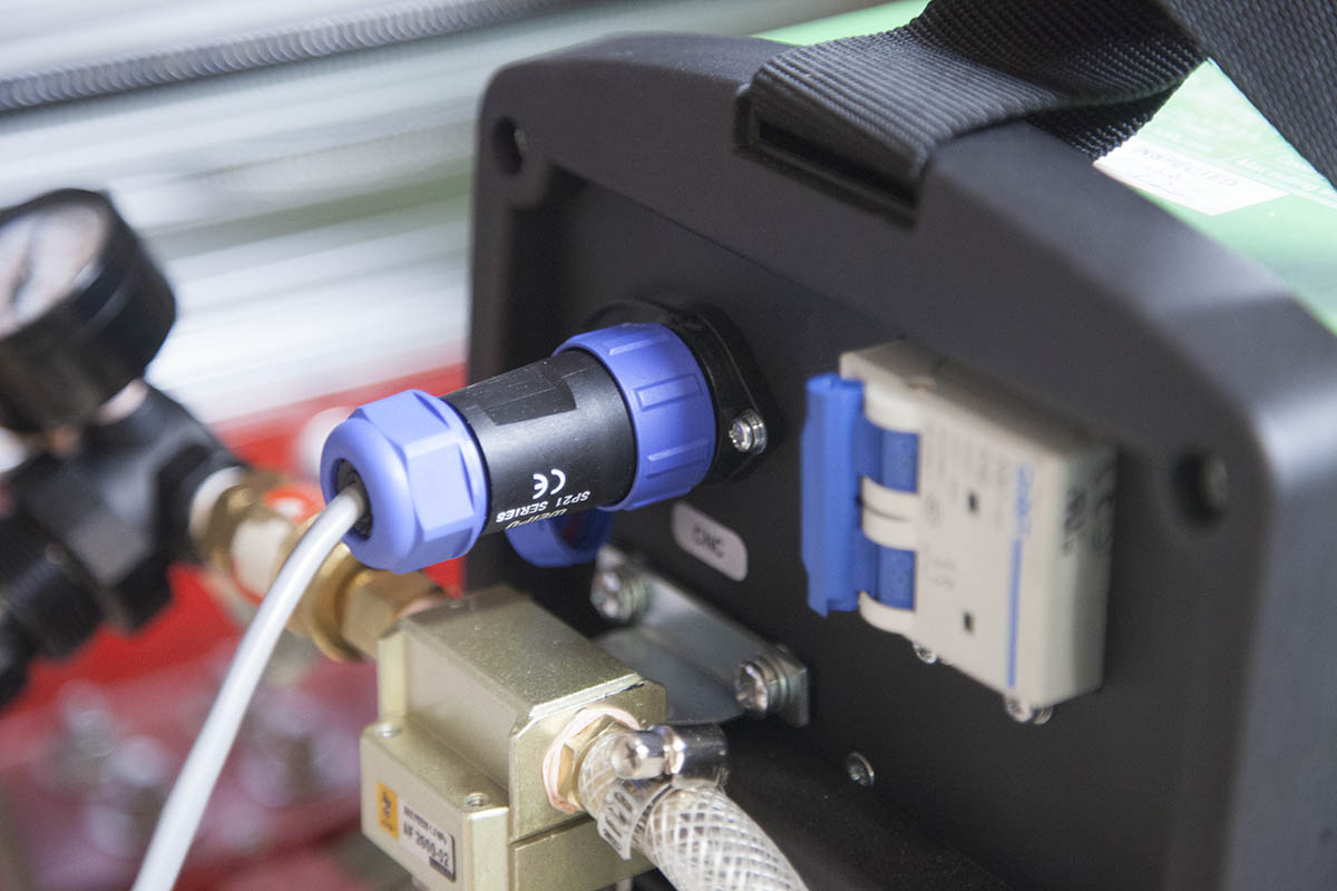
I am using an Everlast PowerPlasma 50S as my plasma cutter.
This is a great plasma cutter. It comes with a PT-60 torch so the consumables are both inexpensive and readily available.
The machine has a built-in CNC port and even comes with the connector.
Here I wired pins 1 and 2 to a relay that would normally be used to turn a router on and off. As a matter of fact, I am using the the other set of connectors so the original router control can remain intact. For more information on the relay wiring please refer to my "Upgrading the KRMx02" workbook.
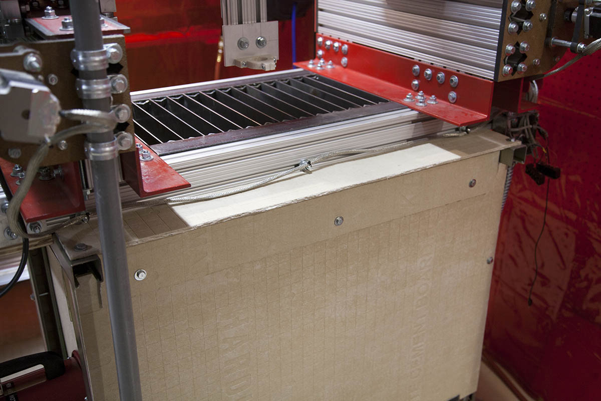
Down Draft Enclosure
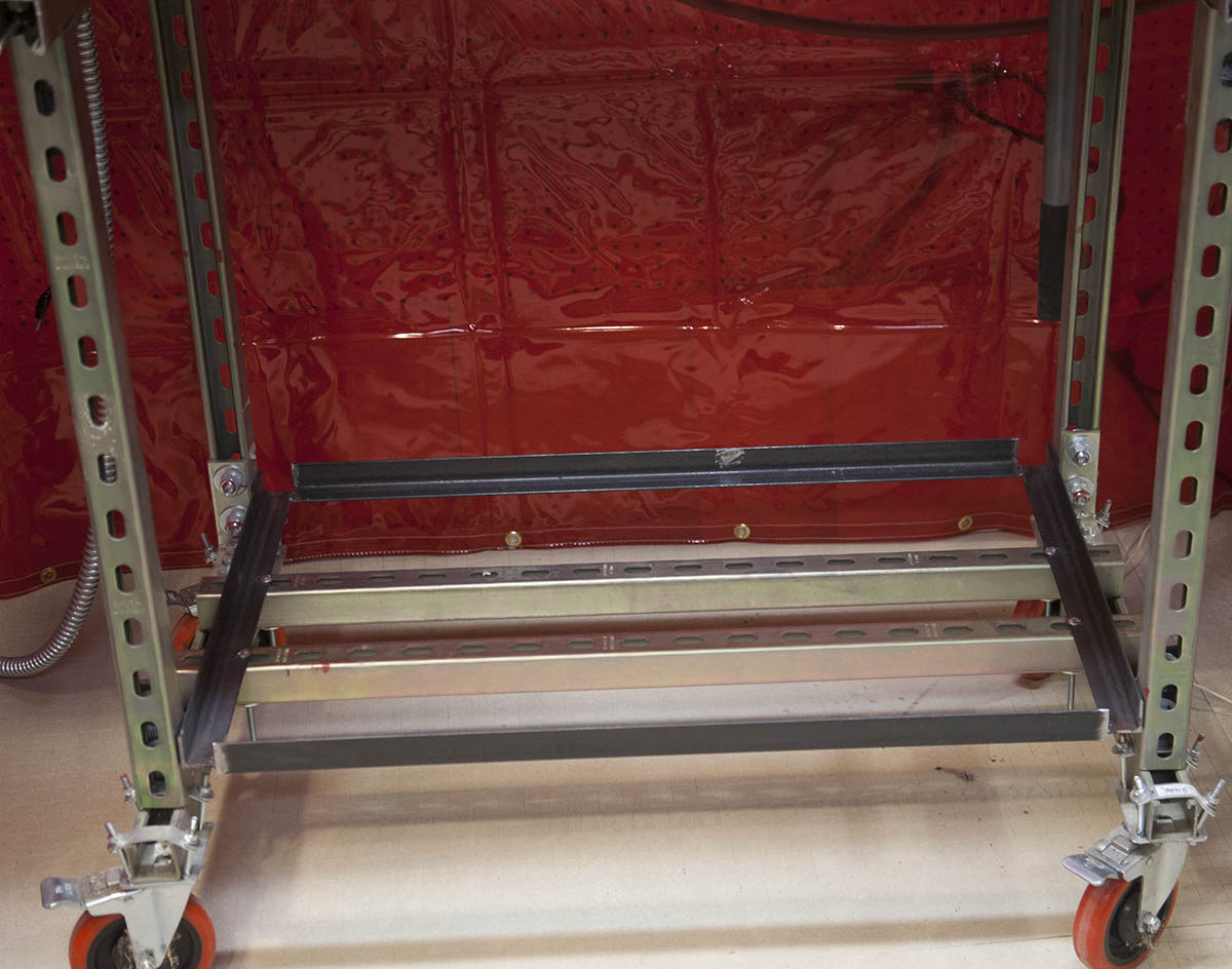

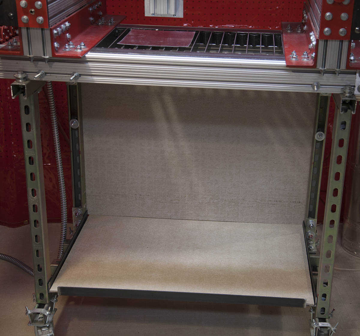
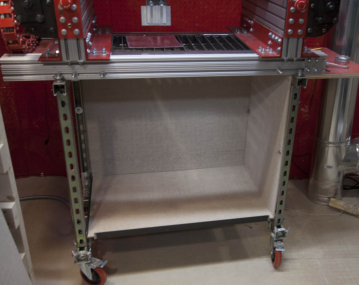
To start I built a frame out of four pieces for 1-1/2 angle and bolted it to the base of the KRMx02 as shown here.
I then cut Hardy Board (Cement board) and attached them to the metal stand using 1/4" bolts.
Eventually I will add a dust tray at the bottom of the enclosure.
The next step in the down draft table is to add the blower.
CAM
In order to do plasma cutting you need CAM software that allows leads. While there are far better CAM packages out there for plasma cutting, here I am using Vcarve Pro.
You will need to add a lead-in to all inside and outside cuts. This is done because the piercing action in plasma cutting will create a larger kerf than the normal cutting kerf.
In addition to the leads, you will need to create a custom post processor for plasma cutting. Unlike a router that starts the router at the beginning of the job and shuts it off at the end of the job, you need to turn the plasma torch on at the start of each cut and off at the end of the cut.
I took the mach3 post processor and made a copy and added the following sections to the text.
In addition, you will need to remove all other M3 commands from the post processor.
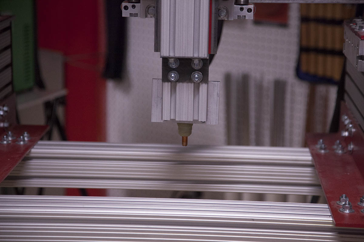
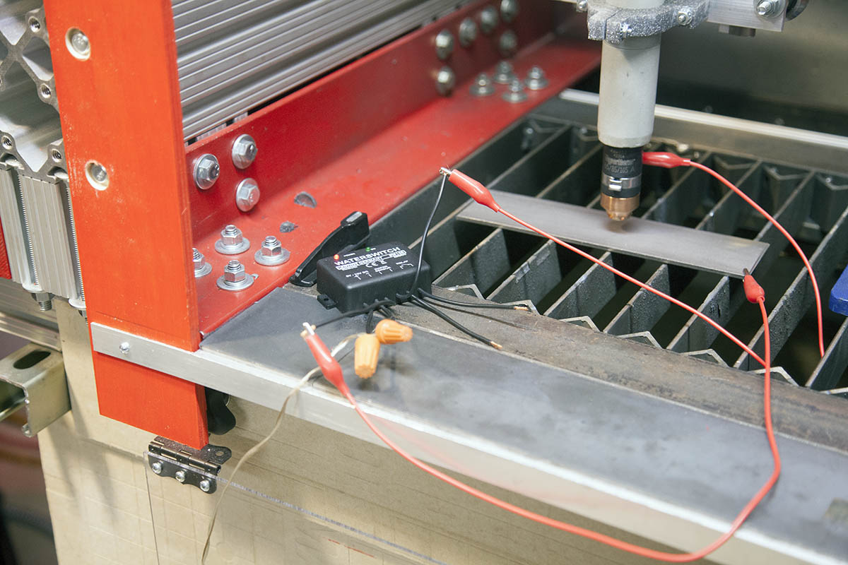
First Cuts
I made a couple initial cuts with the CNC, and so far am happy with the results. I cant dial in the settings yet as my down draft table is not yet complete.
Also keep in mind this is painted metal and since its a small thin sheet, leaves a very burnt surface.

In addition, since these are my first tests I am using rather crappy consumables.
Blower
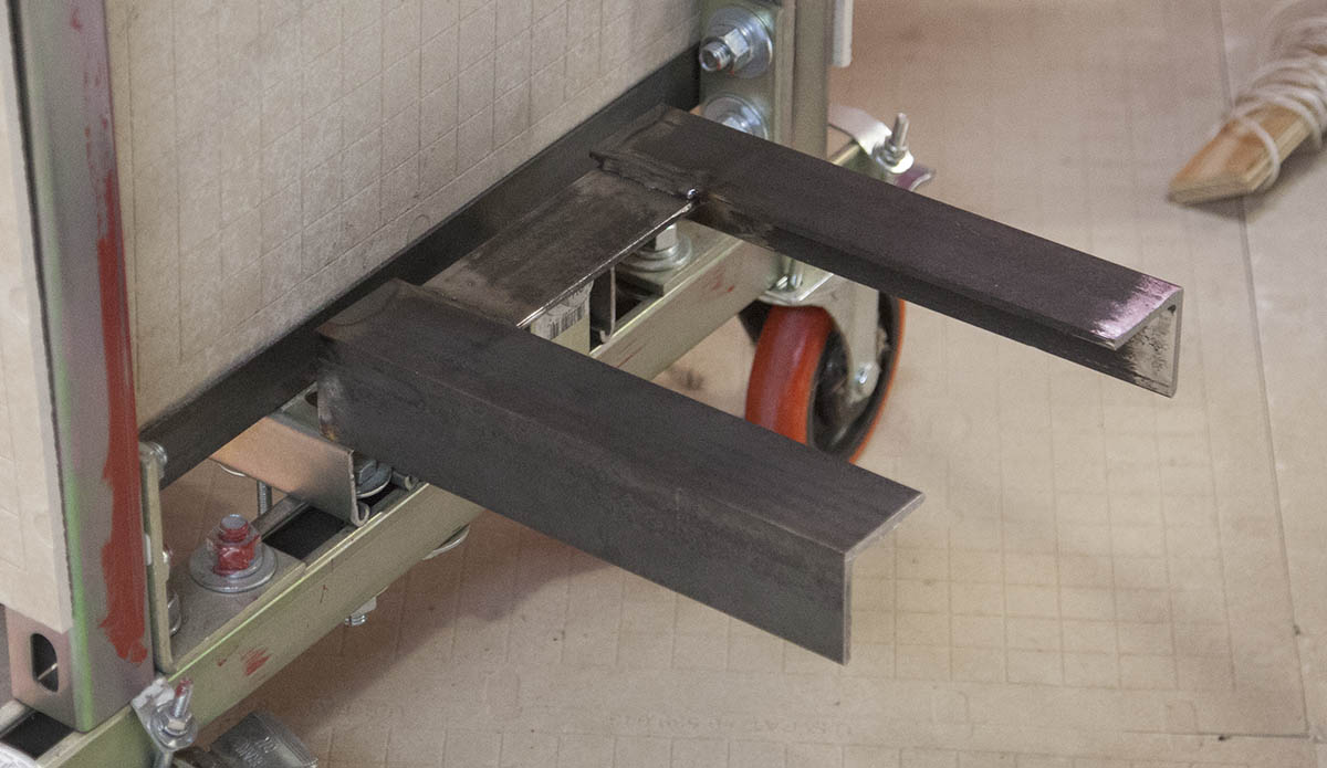
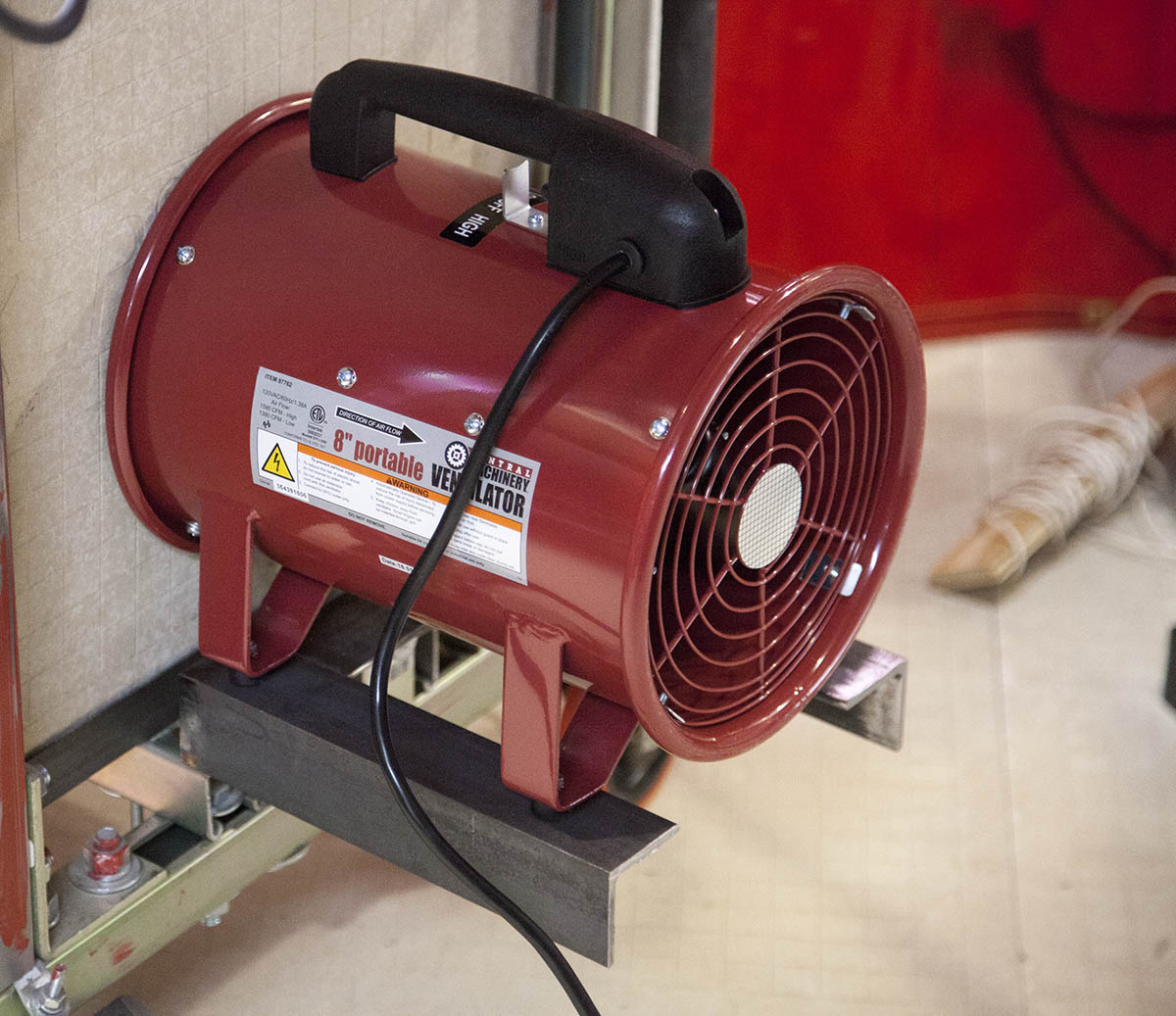
I'm using an 8" ventilator available from Harbor Freight for about $80.
I welded up a bracked and attached it to the base of the CNC stand using large angle brackets. This will be used to hold the blower against the side of the encloseure.
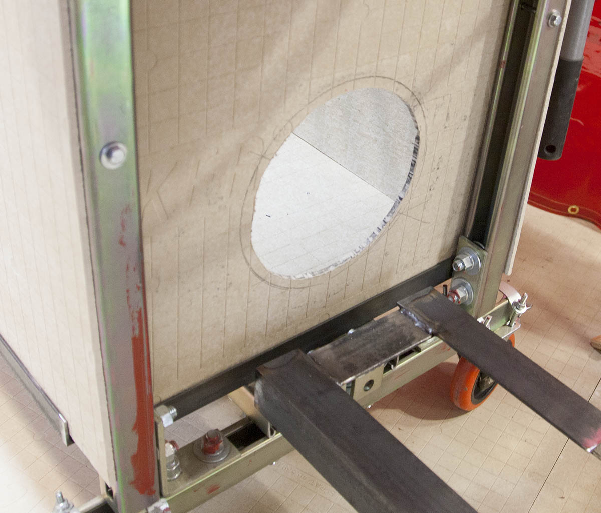
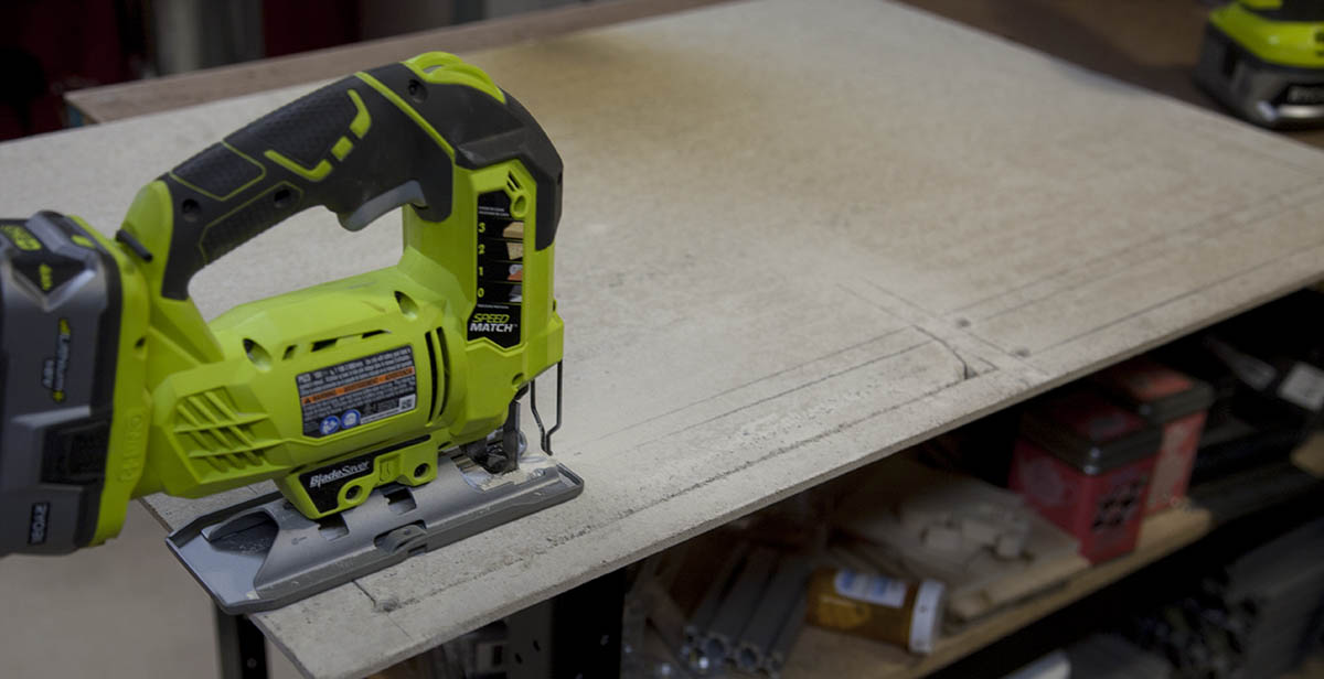
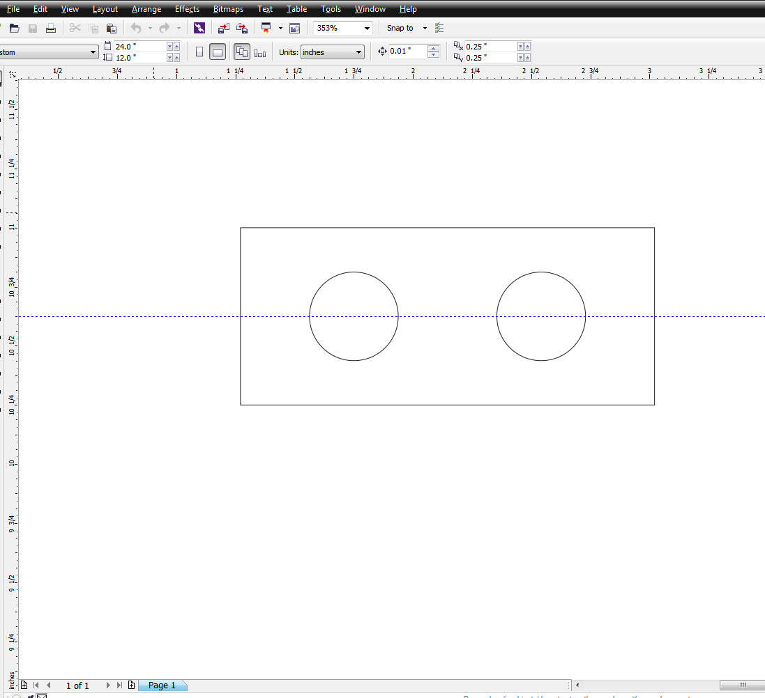
I placed the blower in place then traced the edge. I found the center of this tracing and placed an 8" circle inside and cut it out.
The blower sits in place against the side of the enclosure.
Seal It Up
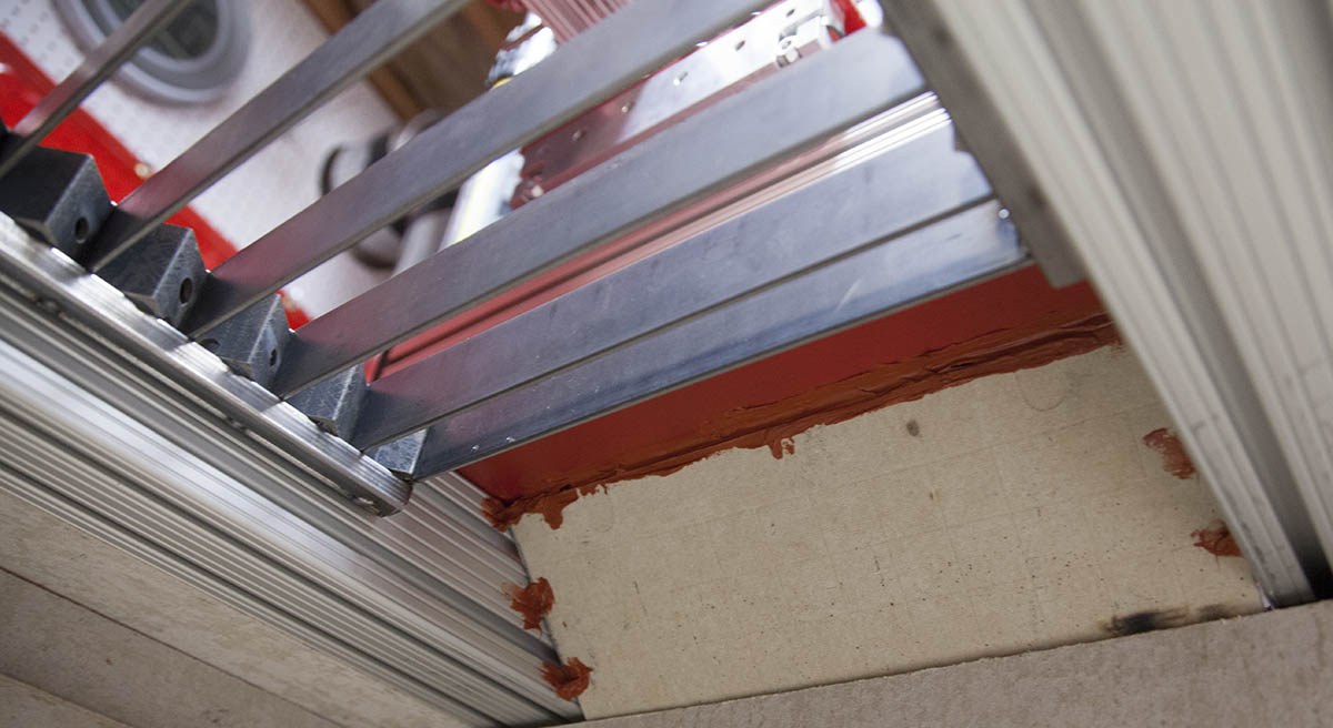
The next thing I did was to seal up most of the openeings. This will provide more static downdraft and keep the plasma cutter from spewing out dust through the openings.
On the sides, I simply cut a couple pieces of cement board and use some high temp RV sealant to hold them in place.
Ductwork
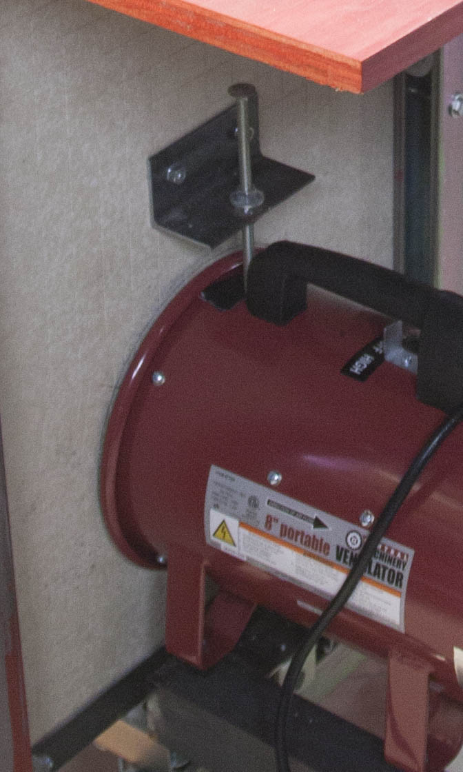
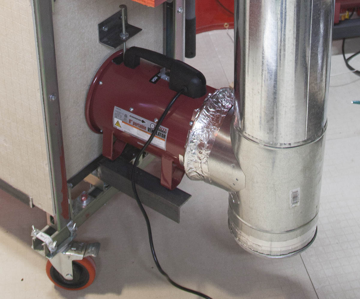
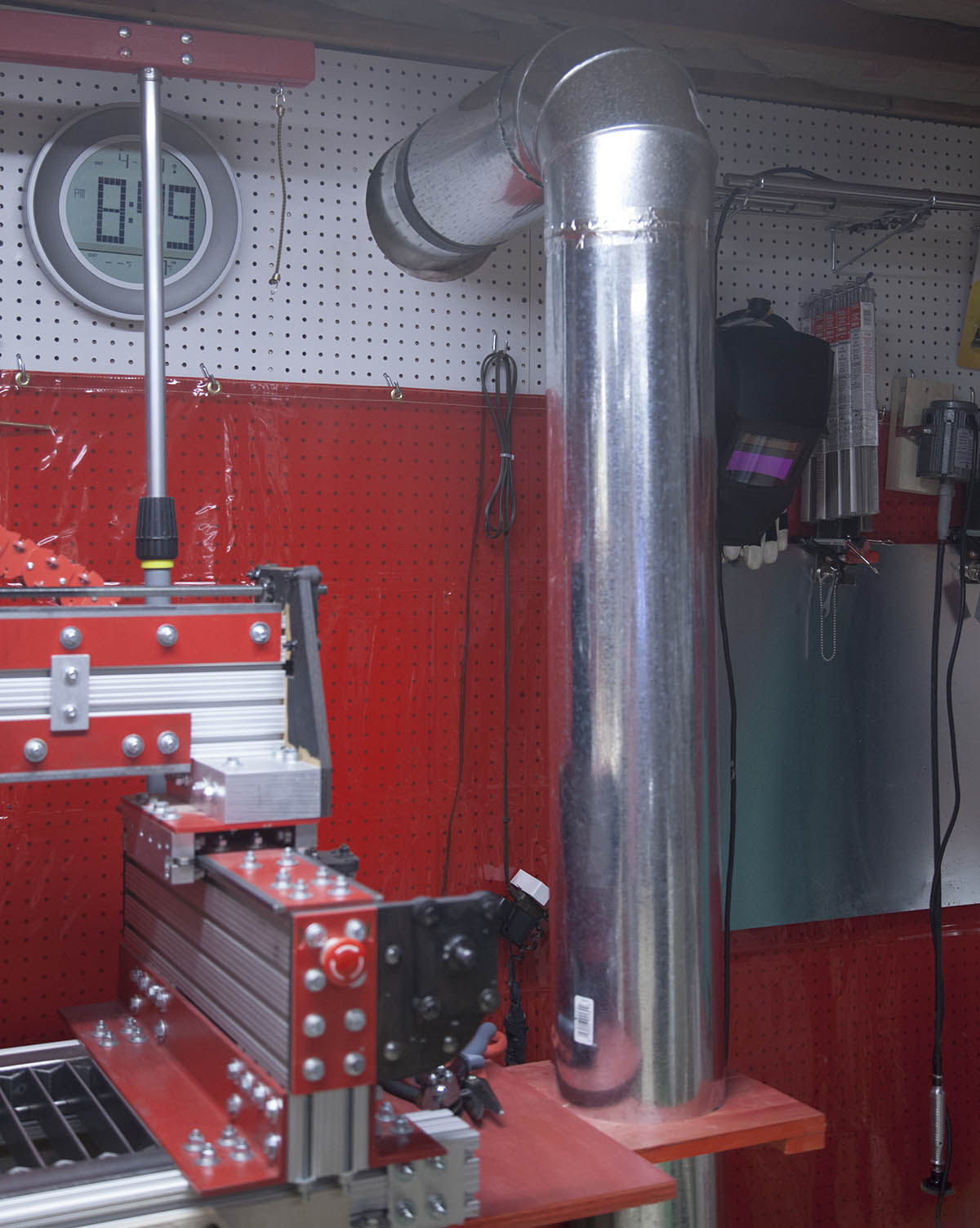
First, I added an angle bracket with a welded nut to allow me to secure the blower.
Next, I attached an 8" T to the blower using metal tape. I also taped a cap to the bottom of the T. This will allow me to clean out pipe periodically.
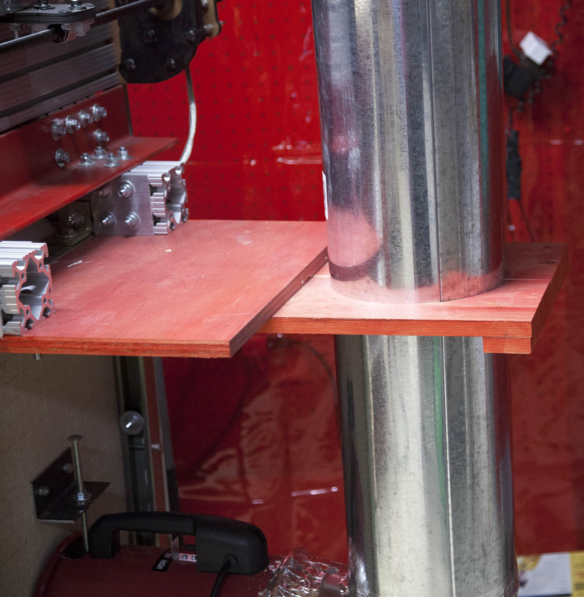
I then added a 5' section of 8" pipe to the top of the T. It is secured with wood brace on the shelf used to hold the plasma cutter.
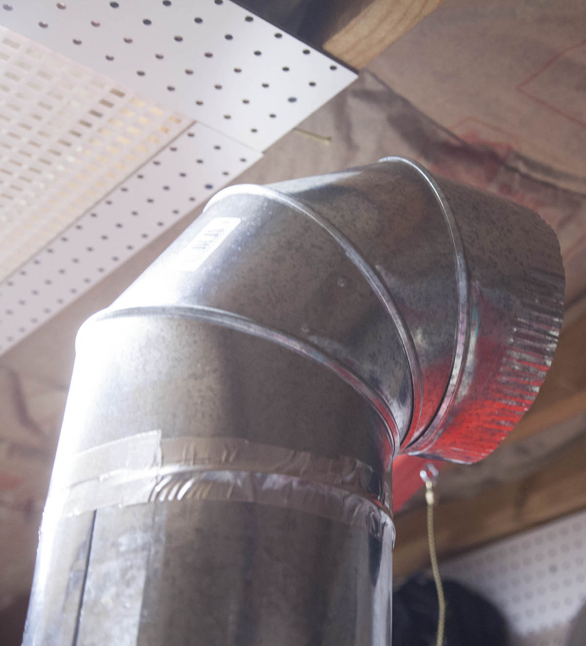
Finally, an elbow was added to the top of the pipe. It will interface to a set of pipes venting outside.
Outside Vent
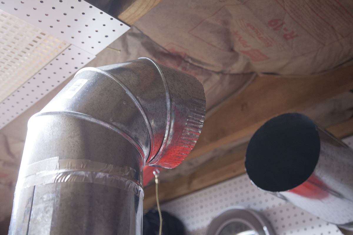
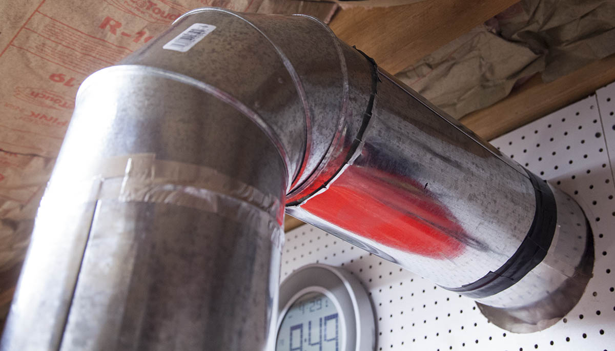
I have an existing outside vent that was attached a standalone downdraft table I built a little while ago. I disconnected that table and added an extension where it comes through the wall.
The idea is to roll this machine so that the mating elbow slides into the flared end of the vent duct work. This way I can pull the CNC out of the way and move the standalone table into position as needed.
First Project
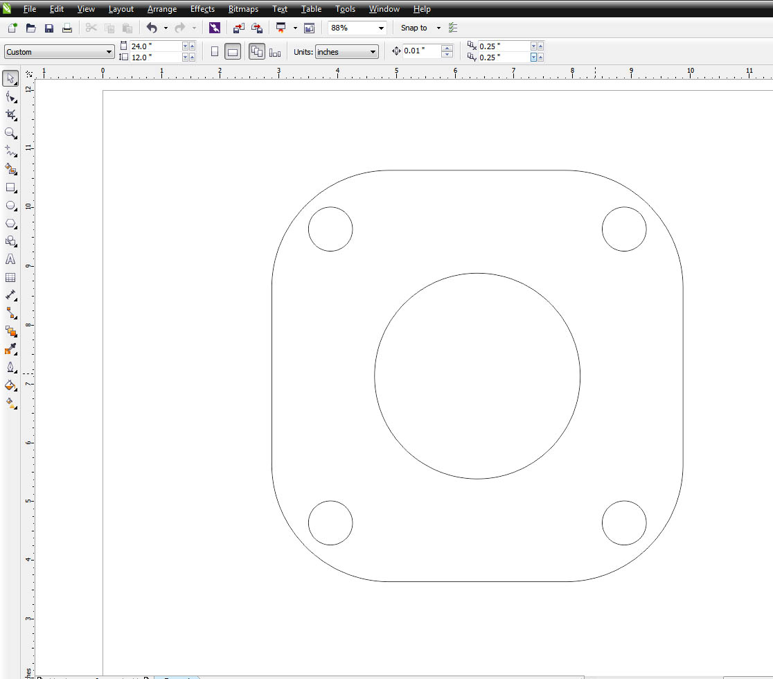
I needed a quick little project to test the downdraft table. So I used some nasty painted steel to create a plate for a chicken waterer.
First, I created the drawings in Corel Draw and exported an eps file.
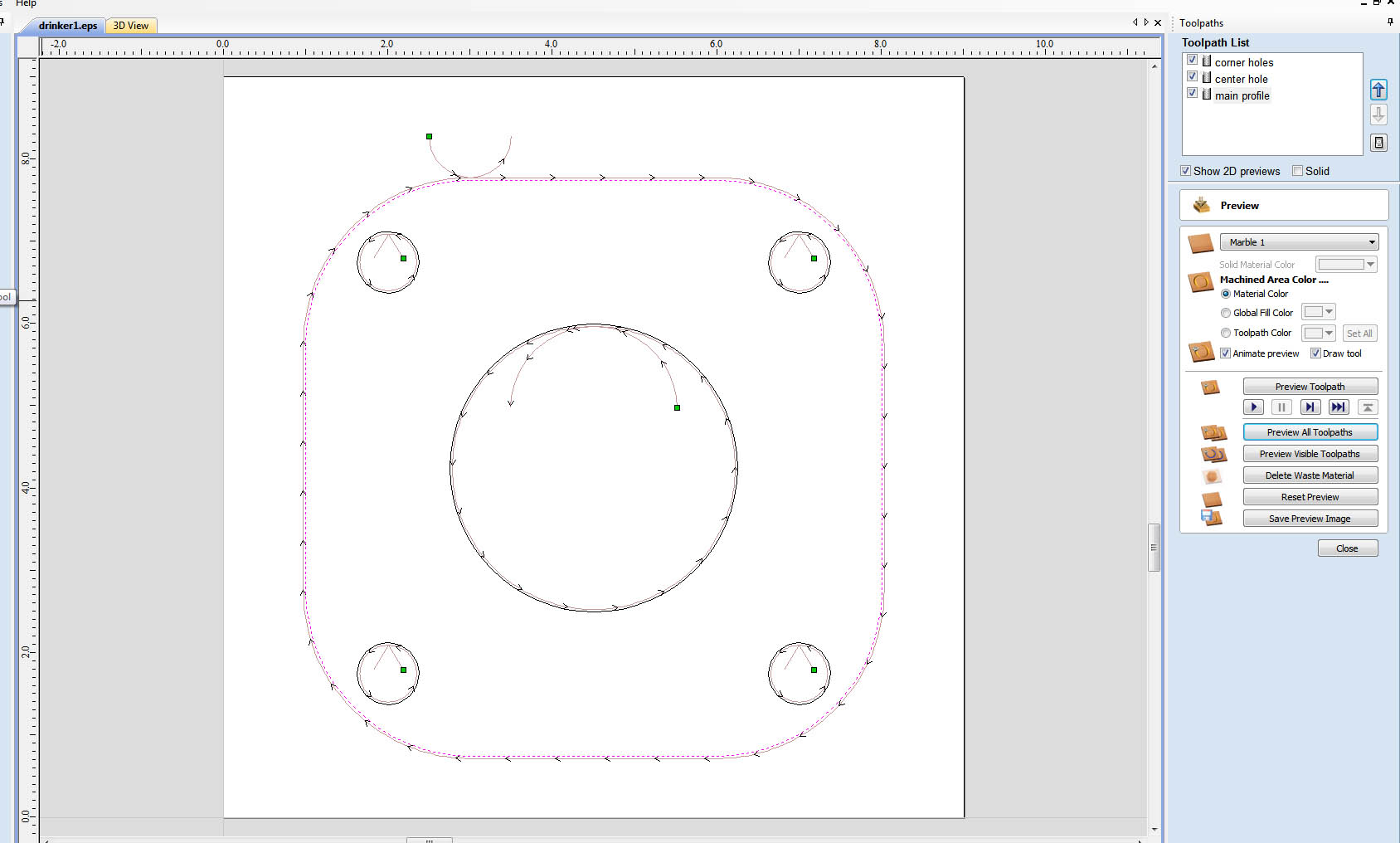
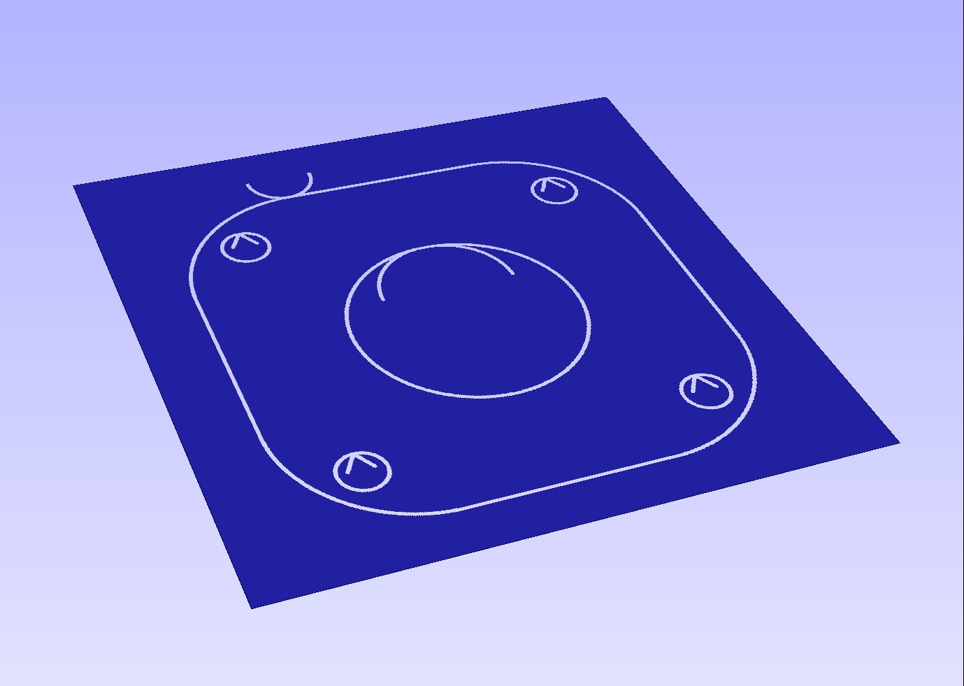
Next, I imported the eps file into Vcarve Pro and created the tool paths. Note the lead-in and lead-outs.
I'm using the same post processing file I used earlier so its not tweaked at all for the consumable or stock I am using.
In any case it will be a good test for my downdraft table.
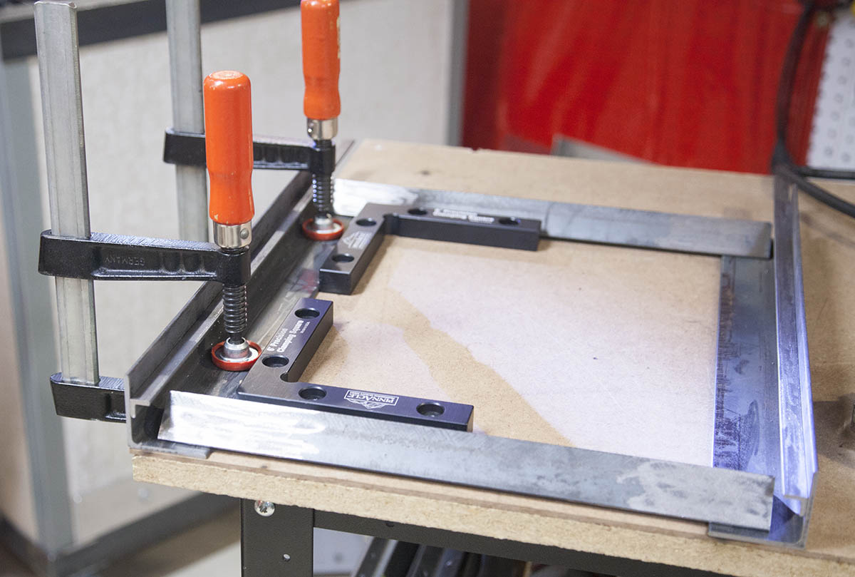
Not only did the downdraft work better than expected, the plasma table worked very well without any tweaking.
Clean-out Drawers
Pulling items that fall into the downdraft is simple enough with the use of a magnet. The problems start once you get a build-up of plasma dust in the bottom of the cabinet. This makes retrieving items a little harder. In addition you have to remove the front panel to clean the cabinet. A couple clean-out drawers can solve both issues.
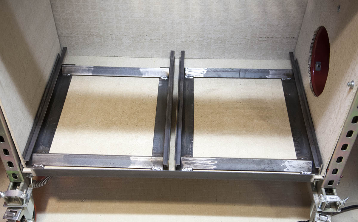
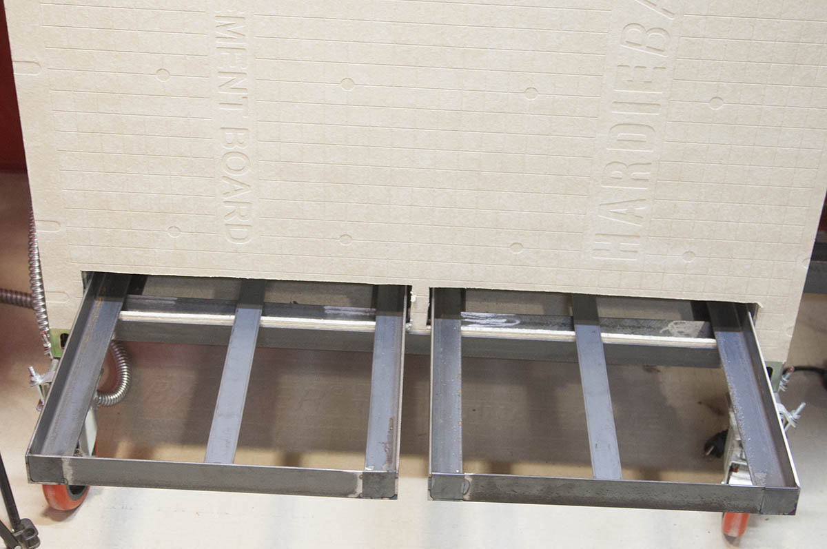
First, I designed and assembled the drawer shelves. These provide a simple sliding mechanism for the drawers to slide.
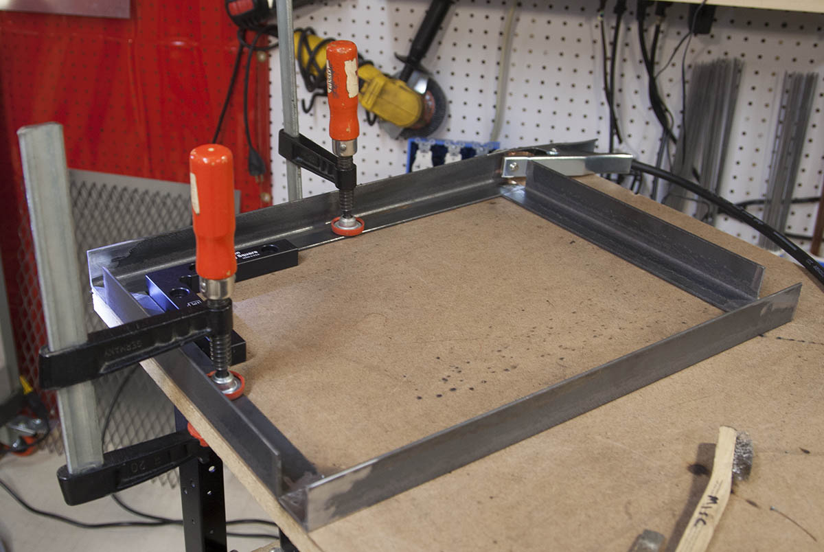
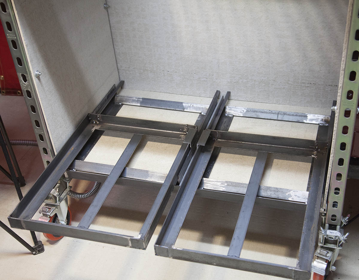
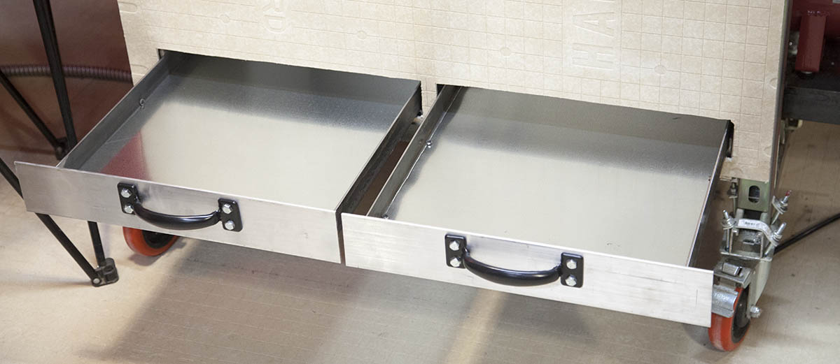
Next, I designed and assembled a couple drawers. I decided to go with two drawers, as a single large drawer can get heavy when cleaning or retrieving a part. I want to be able to open the drawer with one hand.
The drawer cut-outs are then added to the front panel.
Finally I added the drawer front, handles and drawer bottoms.
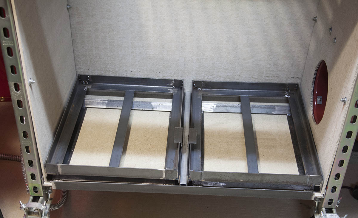
The new drawers work like a charm.
Something to keep in mind when adding clean-out drawers. Multiple drawers will allow debris to accumulate between the two drawer assemblies. Not a big deal but, will require clean-out from time to time.
SheetCam
It became clear that only the simplest parts could be processed with Vectric software. This is because Vectric software is primarily designed for milling operations. It is just too unwieldy to use for plasma cutting operations.
SheetCam, please step forward!
While I have found SheetCam to be very well suited for plasma operations, unlike the Vectric software, there is absolutely not CAD. You must design your part with a CAD program capable of exporting a file that SheetCam will understand.
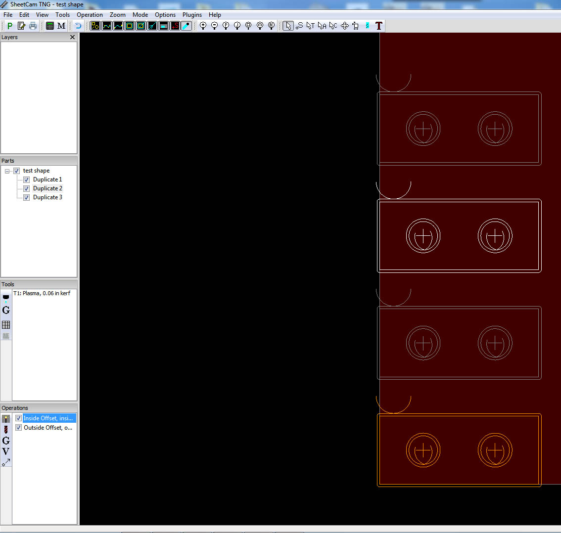
In my case I used CorelDraw to design the part and exported it as a DXF file.
Using the "Import Drawing" function I brought it into SheetCam. I then duplicated the part. Im not going to go into all the features on SheetCam as there are plenty of articles on the web for that. I will say this though you have a lot of control on the Lead-In and Lead-Outs. This allowes you to make some very accurate parts.
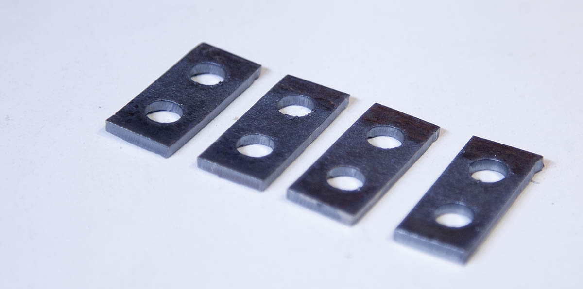
Here is a video of me cutting the four brackets. On the first two, I forgot to connect the ground (work clamp). The parts were still cut and worked just fine.
The second two I started to dial the machine in a little.
Floating Head
A floating head on a plasma machine is a good first upgrade. It will allow you to reference the surface of the stock before each cut. This is helpful when cutting warped material. Even if it warps during the plasma cutting operation.
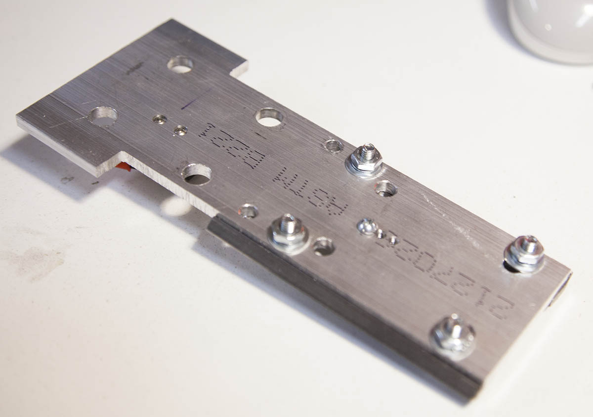
First, I cut out a piece of stock that would mount to my main Z-beam. The four large holes on the top are the holes for mounting to my Z-beam/rail. This will become my floating mount.
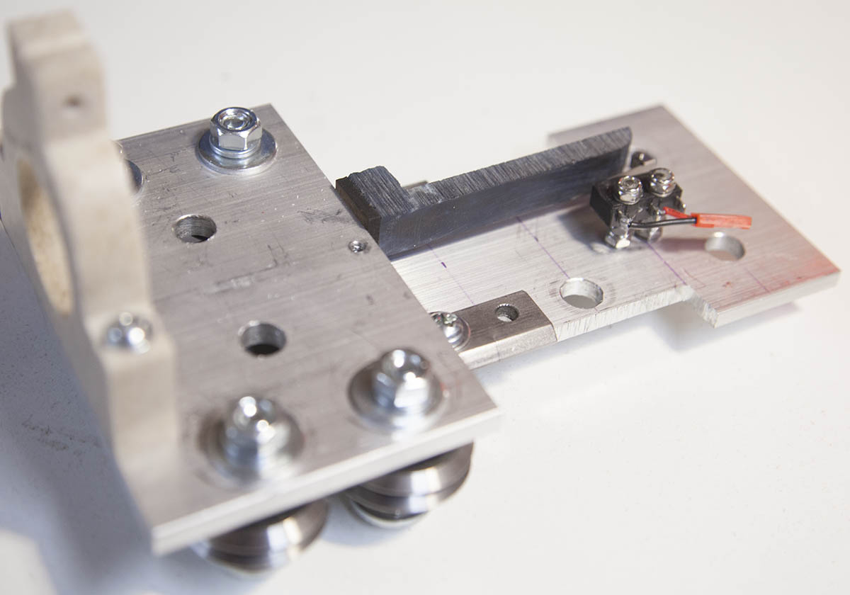
Next, I added two short pieces of hardened V-rail to the edge of the mount and installed a roller switch.
I then took another piece of stock and mounted four V-groove bearings with eccentric bushings. This will be the actual floating head.
The head contains the torch mount and a piece of plastic that engages the switch on the mount.
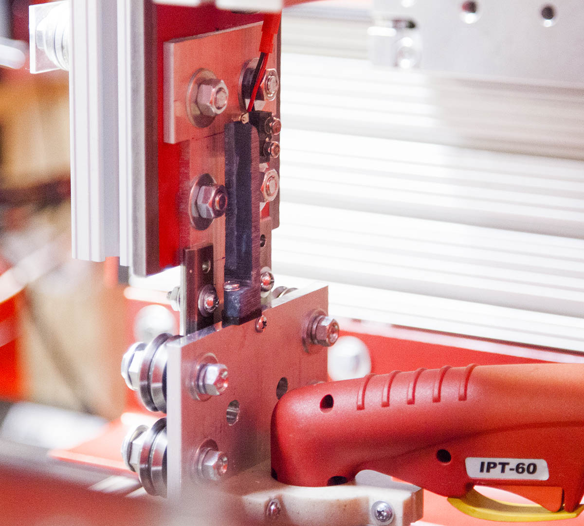

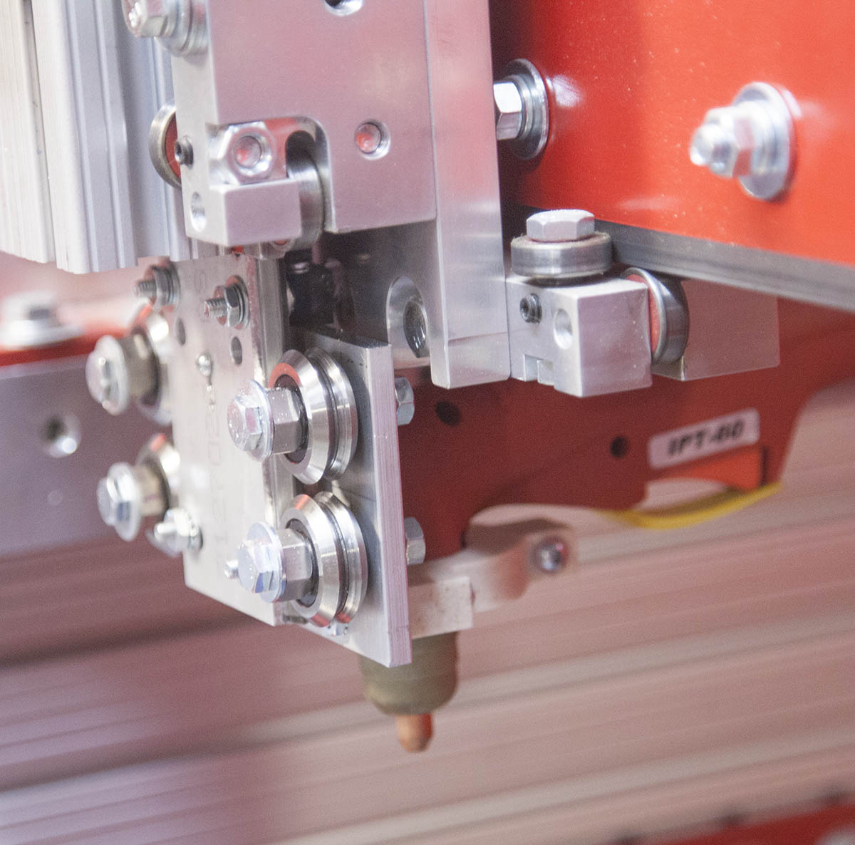
The mount is connected to the Z-beam/rail and the torch installed.
In order to use the floating head I had to create a new post processor file. The highlighted section is the items I added/replaced in the OnPenDown Event.
Most use the post to reference the Z-axis by using the switch on the floating head as a limit switch. I have a seperate limit switch for my Z-axis so I use the switch on the switch on the floating head as a probe.
This then allows me to probe the surface of the stock at any time with the various probe scripts. This is good when I don't want to use the probe with each cut.
Here is a quick test showing the floating head in action.
Marker
One advantage of a floating head is that you can easily add a marker to help visualize a cut.
As a welder, we often will mimic a cut to see if we are properly setup. By adding a marker to a CNC you can do the same.
After looking at the result from this drawing, I can see that I need to move the CNC to the right a little.
Door Lock Pinion Gear Workflow
My first real part.
CAD Design:
I design a part in Corel draw and export a DXF file.
The part was designed to be cut out of 2" angle iron.
CAM:
The DXF is loaded into SheetCam and the cut paths created. The Gcode is then created with the modified (floating head) post processor.
Control Software:
The Gcode is then loaded into Mach3. SheetCam has a real cool feature where it can talk directly to Mach3 and tell it to load the Gcode automatically.
Test:
I run a test where you can see the floating head in action.
The Cut:
I then cut the part. It has very little dross, but the center hole is a little small. This is because the kerf I have set in SheetCam is a little too much. It is currently set for .06" I will change it to .05 on my next cut.
The Stats:
I am using HF consumables.
Amps=45
Speed=100IPM
Cut Height=.06"
Pierce=.15"
Everlast 50s Consumables
I have been having problems locating different size consumables for the Everlast PT60 torch. While Everlast claims the consumables are more available than the original Trafimet torch, I have found this to be far from true.
This is what I have found thus far:


Everlast 50 Amp Consumables
These are the original consumables. They have a 1.2mm hole. I only recommend these if you are cutting material thicker than 1/4" thick.


Harbor Freight 40 Amp consumables
The Harbor Freight plasma cutter uses a PT40 torch. These consumables will work with the PT60 torch.
The nozzles have a .9mm hole which make them a nice fit for the Everlast. With these consumables you can make a finer, more detailed cut.
They sell these in a set of five nozzles and a set of 5 electrodes. I have not seen any difference between the harbor freight electrodes and the Everlast electrodes.
These consumables are great for thinner materials.

Drag cutting consumables
These are advertised as drag cutting nozzles. While they do work, you cant use them on anything more than 30 Amps as the stick to the steel because they are not shielded.
That said they make very short work on thin gauge sheet metal at 20 Amps.
They come in sets of 10 electrodes and nozzels for about $60.
I am not the only one to notice the lack of reliable consumables for the Chinese made plasma cutters. Hopefully this will change in the future
8/1/2016 Update Experiments Successful
I have moved on to my first new plasma build prototype, but wanted to get you caught up in the upgrades I made to my KRMx02 plasma machine.
Hypertherm Powermax 65
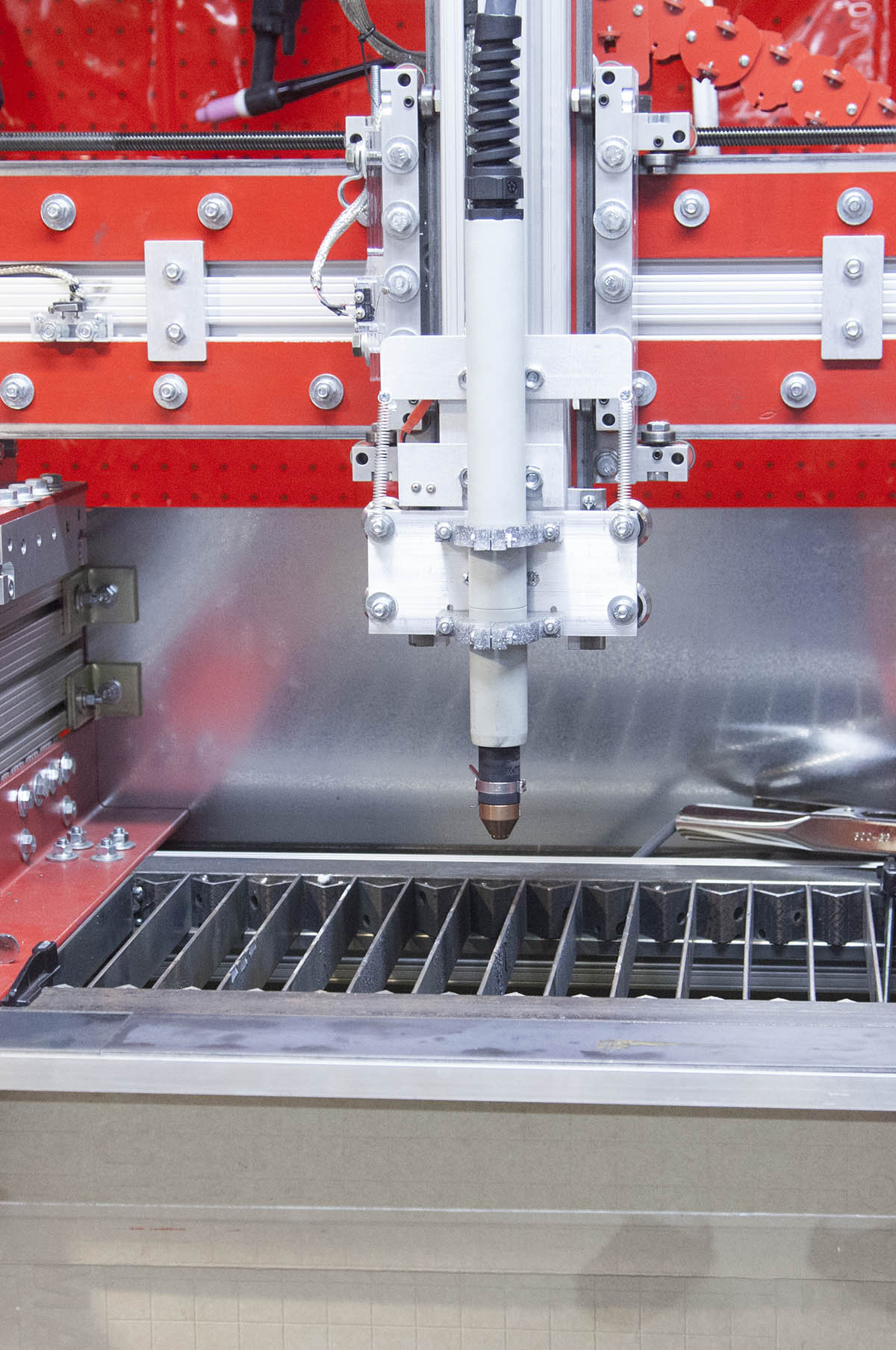
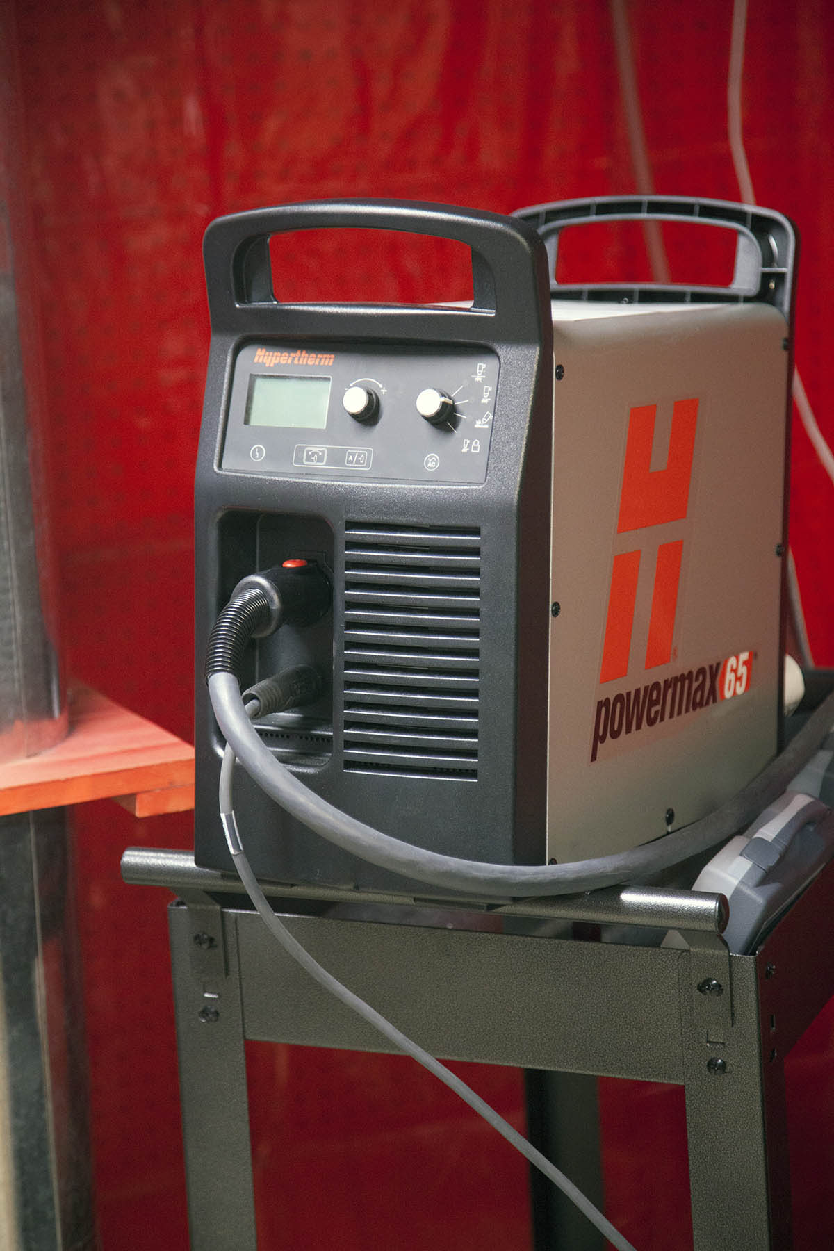
I installed a Hypertherm Powermax 65 plasma cutter with a machine torch to the system.
The Hypertherm consumables are more ready available. In addition I have found the consumables offered by Hypertherm to be more CNC friendly.
The only thing I had to do to the CNC to accommodate the Hypertherm was to move the torch mount to the front of the machine. This also meant I had to rebuild the floating head.
Rack & Pinion drives
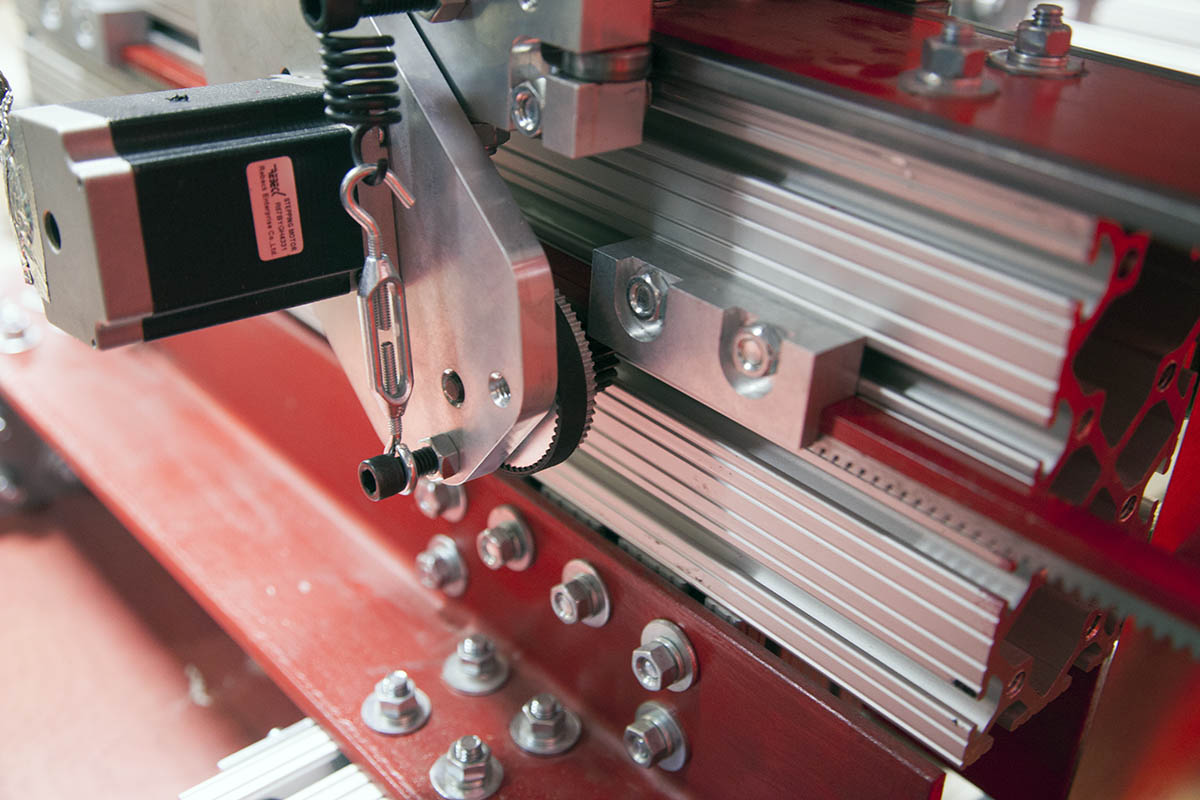
I converted back to the stock Rack & Pinion drives on the KRMx02.
Honestly I did not find any performance or quality difference between the 5 Start ACME screws and the R&P drives.
The R&P drive does, however allow me to do something I cant with the ACME screws.
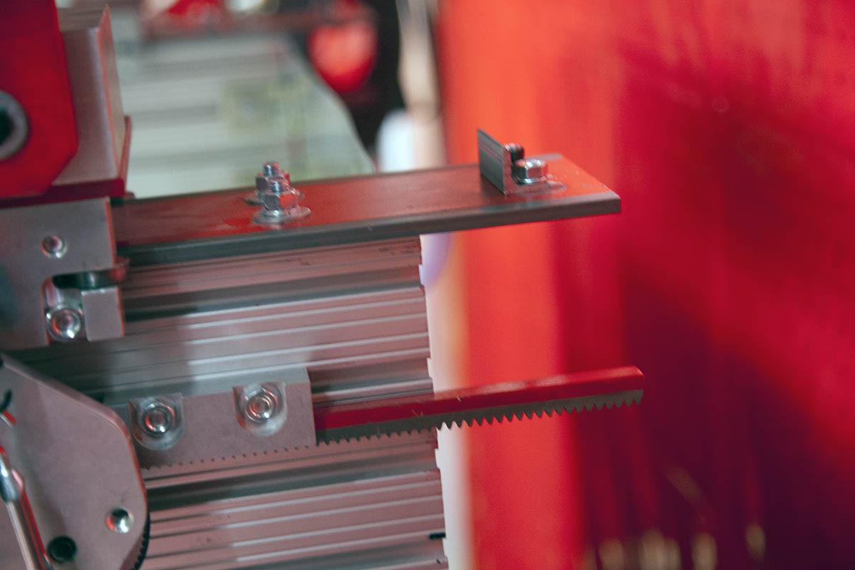
The R&P drives allow me to extend the guide rail out past the end of the Y-beams as shown here.
This allows the front mounted torch to access the full depth of the cutting table.
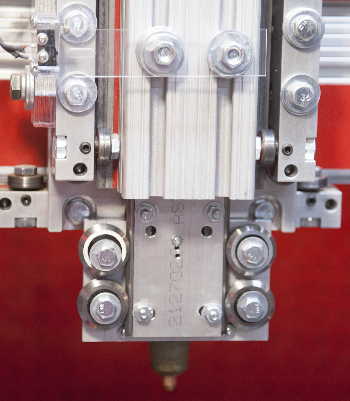
Ohmic Sensor
I added a Ohmic sensor to the Hypertherm machine torch. This allows me to touch off the stock without deflecting thinner metals. In addition it is very accurate.
I kept the floating head as a backup. If the Ohmic sensor fails due to rust or paint, the floating head will activate the Z limit switch and shutdown the Job.
Please note, there is no Ohmic option on the everlast torches.
Spark Gaurds

I added a rear spark guard and a folding clear front spark guard.
Thee help to keep some of the larger debris from escaping the down draft.
Conclusion

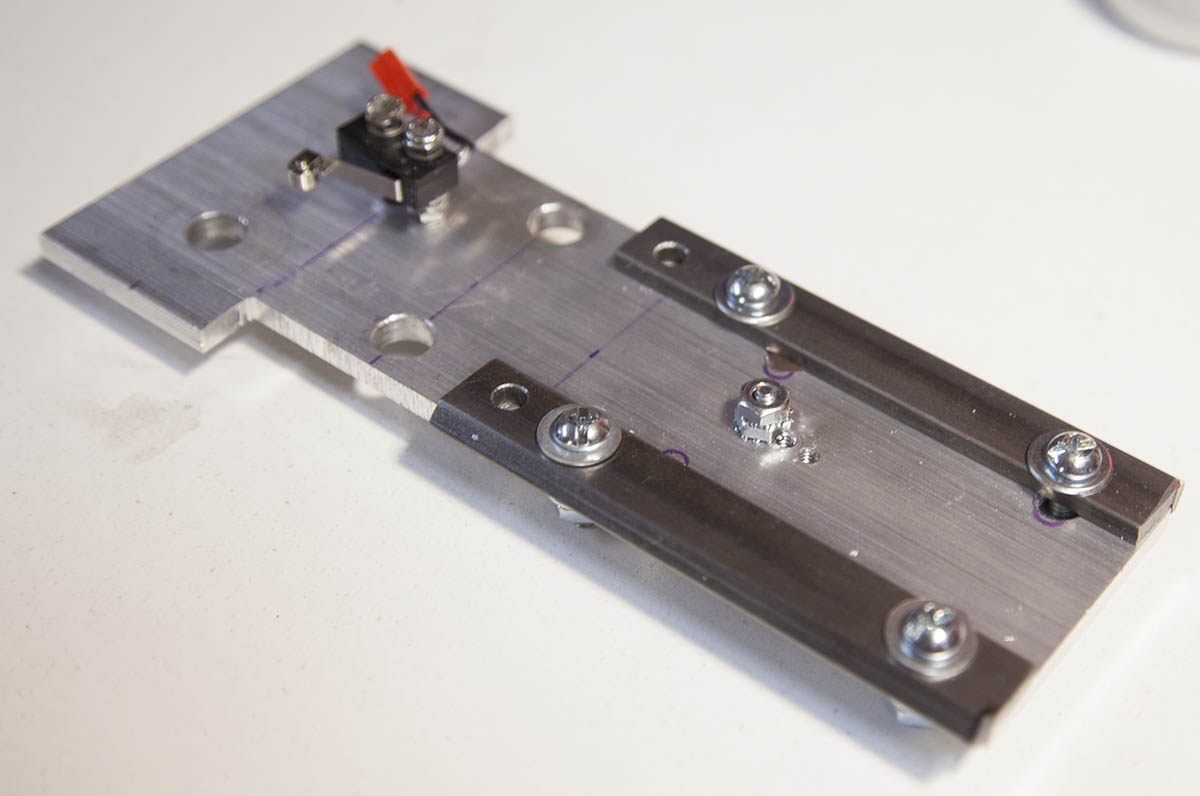
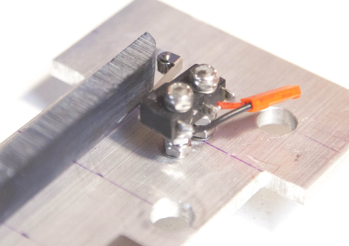
This small plasma CNC plasma cutter may well be on of the smallest CNC plasma cutters, but it does a great job at fabricating small parts.
This is a fixture I made with this machine.It is used to hold small pieces of steel angle and square tubing in place so it can be cut with the plasma cutter.
It has indexes so that the stock can be flipped and placement can be maintained.
I use it so much that I have not taken it off the machine since I attached it.
I have designed a new machine called the CNC Construction Set or CNCCS for short. It can be operated as a standard milling machine or as a plasma cutter.
See it here: