

Once my fixture was completed I wanted to do some preliminary tests before jumping into the whole PCB CAD thing. These tests will let me know the kind of resolution I can expect when I do move to actual circuit design.
The test is a single sided board test utilizing a 100mm x 70mm board. You can pick them up here:
Mounting your PCB
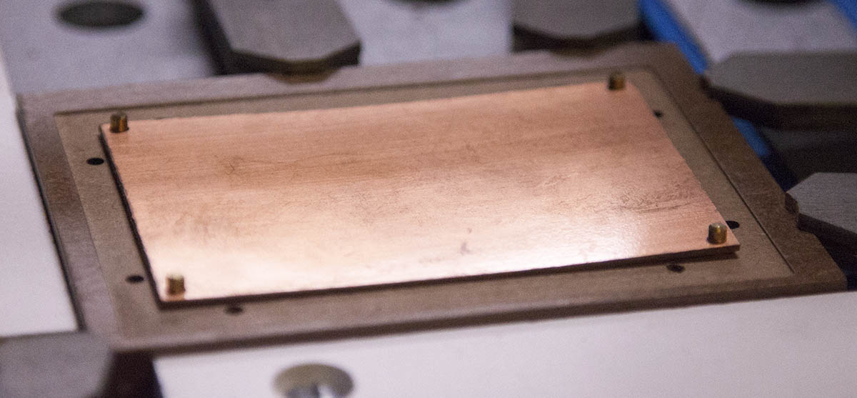
Place the alignment pins into the four alignment holes ans slip your prepped PCB over the pins as shown here.
Notice how the left and right sides of the board are bowed up. This is ideal. Originally this board was bowed the other way, which would have left the center of the board raised off of the fixture. This is common for single sided boards.
To compensate for this, I purposely bent the board in the opposite direction with my hands before slipping it over the pins.
Note that I am using a fixture made from MDF for these tests.

I inserted eight #6 x 1/4" machine screws and tightened them until they pulled the sides of the board down.
This insures that the board is flat against the fixture on all sides.
Note that over time the board will resume its original shape.
Get Ready to Mill
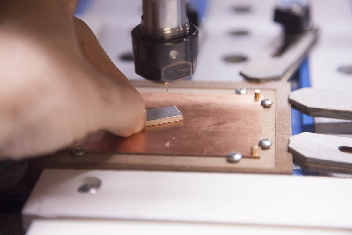
I have inserted a 20 degree 1/8" carbide V-bit into the spindle.
You can purchase one here:
Once the bit was installed, I set the tip to the surface of my PCB using a probe.
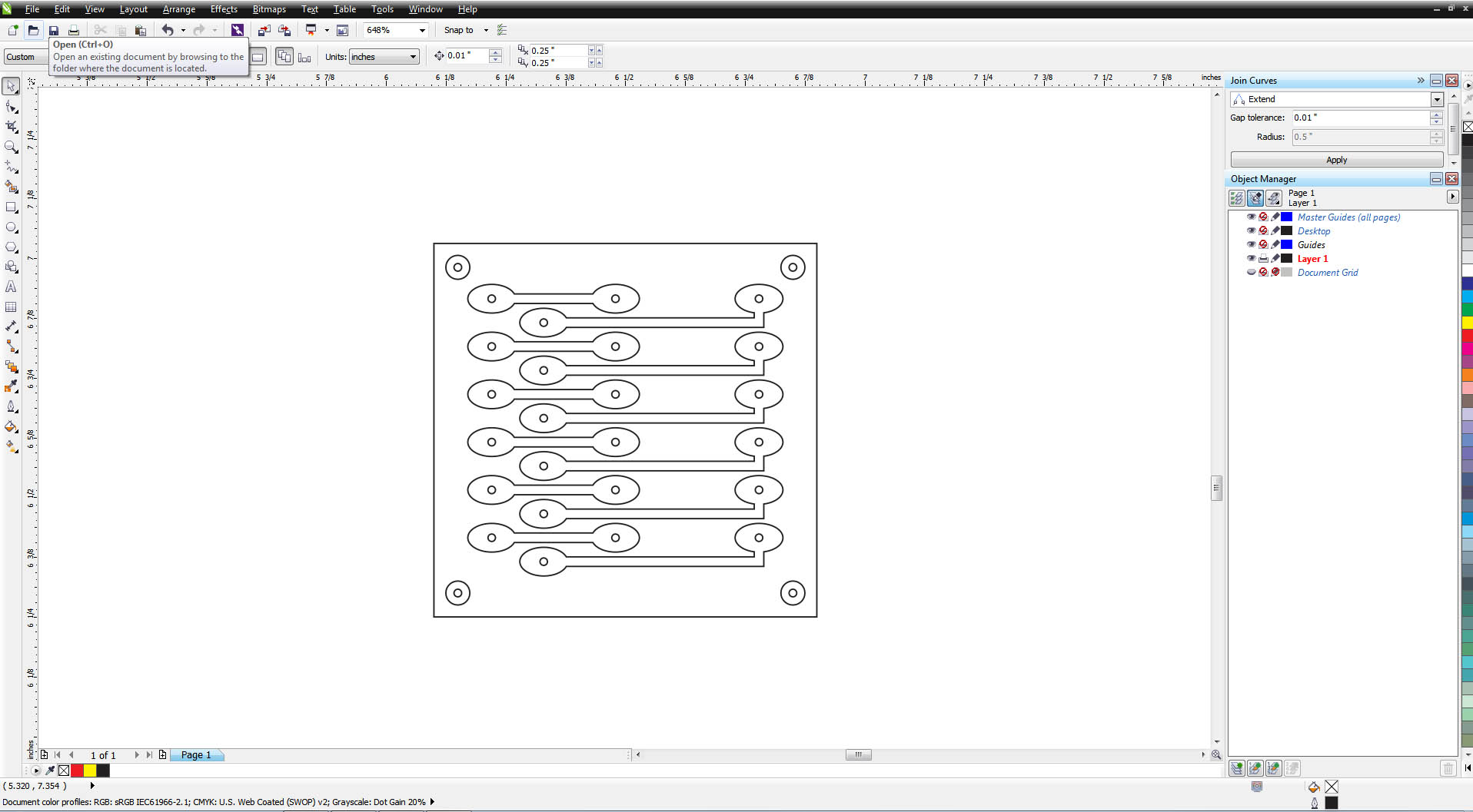
The Test Design

I am using the design shown here. The outside diameter is 1". The small rectangle array above the text is spaced .03" apart.
The array beneath the text has a spacing of .02"
The outside circles are .05" apart.
The design can be found here:
Lets Do It

I created a Gcode file that will mill the design .01" deep.
You can get the gcode file here:
I couldnt be happyer with the results.
Second Test


I decided to make up a little board that utilized traces and give that a shot.
The actual size is about .8" square with some traces that were routed through some pads that were .1" apart. You can get the files here:
How did it turn out?
Even without resetting the Z reference and mill near the center of the board, it turned out perfect.
Even without autoleveller software or a vacuum hold down, the tests were a great success. It's time to make a couple real circuits.