
What is PCB isolation routing?
Isolation routing is when you take a blank PCB and rout (mill) around the traces, thus isolating them. This is done with a very small end mill or V-bit. Holes are then drilled with a very small drill bit.
On dual sided boards both sides are milled. This allows you to create very complex boards.
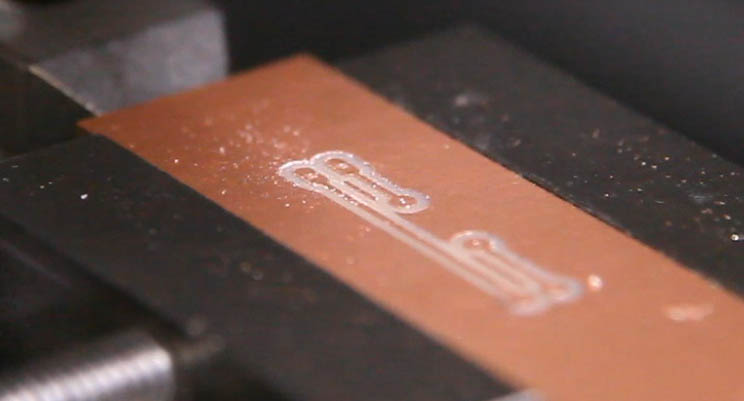
This very small single sided board only took a minute to mill using my KRmf70 CNC. Having such a small size, it does not need any special hold downs or auto leveling software.
What I will Show You
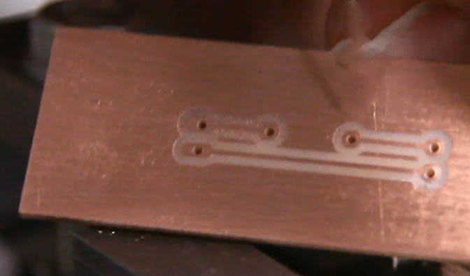
It has been a while since I have done any isolation routing. This is a PCB board I created on my old KRMx01, back in 2011.
This was a 100mm x 70mm 2 sided board. It was used to mount a microcontroller that enabled remote control of a fairly robust set of robots I used in the 2012 engineering fair is Washington DC.
The system I am using here has the boards indexed to a set of pins that can be inserted in the center of the fixture. It worked pretty good, but can have issues if the boards are slightly bowed.
The new system I will be using has index pins drilled into the board and fixture. The board is simply flipped and the X axis reference changed in order to mill the second side of the board.
Leveling the PCB
I will be using a 20 or 30 degree V-bit in order to isolate the traces. The flatter the board can be placed against the fixture the finer the isolations that can be milled. This means more compact traces can be used for smaller and more detailed boards.
There are number ways to achieve this kind of board flatness. The first thing I do is to mill the surface of the fixture that the board will sit on. If the board is not bowed, then you can achieve a great deal of detail without resulting in any other measures.
If the board is not flat its self, then it will probably bow up in the middle on one side or the other.
- One brute force measure is to provide a hole in the middle of the board where you can screw it to the fixture. The down side from this is that you loose valuable space on the board.
- Another approach is to use a vacuum system to pull the board down in the middle. This does not loose board space, but adds some complexity to the system. The main advantage here is that the vacuum system will work with any software/hardware combination. However, if the board thickness is not uniform, the vacuum system can only help so much.
- The last approach is to use some auto leveling software to probe the board and calculate offsets for each milling operation. This system adds complexity to the workflow, but is probably the most accurate. The downside is that this system needs to probe your board and capture/store the results. This will not work on most USB based CNC interfaces.
Software and System
I will be using a parallel port controlled CNC utilizing Mach3 control software on a Windows PC. The CAD software I will be using is Eagle v8.2.1. The Eagle software requires a plugin called pcb-gcode. I will be using version 3.6.2.4 of this. For the auto leveling, I will be using purchased version of Autoleveller currently at 0.8.7. There is also a free version (.077) that I will also be playing with.
I will be posting links for downloading the various components. Note that you will also need Java for windows. In my case I'm using jre-8u131 for 64 bit.
Please note that the system I am using to run the above software, is not the machine that is doing the actual milling. Most of my CNC PC machines are fairly low end machines made to be as small and shop worthy as possible. In my shop I run a couple very large Windows works stations and this is where I will be doing my circuit design. My various CNC machines will be acceding the gcode created via my network.
Your actual setup will probably be different, but should work fine.
Where I am Going
Keep in mind that this is a work in progress. I am always trying to find easier, more productive ways of doing things. If I come across something in the future that does not jive with the content that I have created, I will make changes as needed.
A good example is the Autoleveller software. After much experimenting and research, I found that it is not compatible with most USB CNC interfaces. This includes both the purchased and free versions of Autoleveller. The simple reason behind this is that when you are using a USB based controller, you are off loading much of the Gcode handling to the USB device. Most USB devices dont support many of the features that Mach3 offers, such as provideing the mechanisms to record and store multiple probe attempts.