

In this write-up, I am going to show you how I built this very simple walker. Unlike many toy walkers, It have full motion control.
Forward
Reverse
Turn Left
Turn Right
History
I started Kronos Robotics in 2004. One of the first projects in those early days was a workbook to take you through the process of building your first walking robot.
Back then CNC machines and laser cutters were very expensive and not meant for the hobbyist. The components were meant to be cut with a scroll saw. For this reason, most of the cuts were strait cuts. The design utilized 1/8” birch plywood, which at the time was very inexpensive.
Throughout the years, I created various variations based on the original design concept.
This particular design was one I did for Servo Magazine for a scroll saw article.
This is a smaller mini walker utilizing smaller mini servos. It was a three-part series done for Servo Magazine.
How it Works
The walker is designed to use three servos in order to keep the cost and complexity to the minimum, and still retain the ability of full motion.
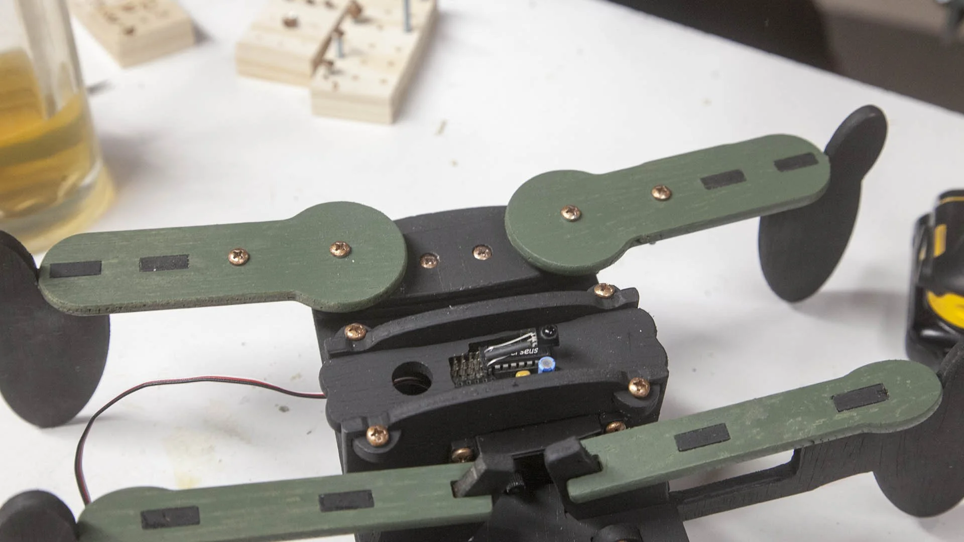
Two of the three servos are mounted in the front.
Please note that this walker was designed to use standard servos.
The front two legs are connected directly to the servos.
The two rear legs are mounted to the frame using a couple spacers and washer bushings.
The front legs are connected to the rear legs with two bars. These bars can be mounted on the top of the legs or on the bottom, as shown here.
When the servo moves the front leg, it also moves the corresponding rear leg.
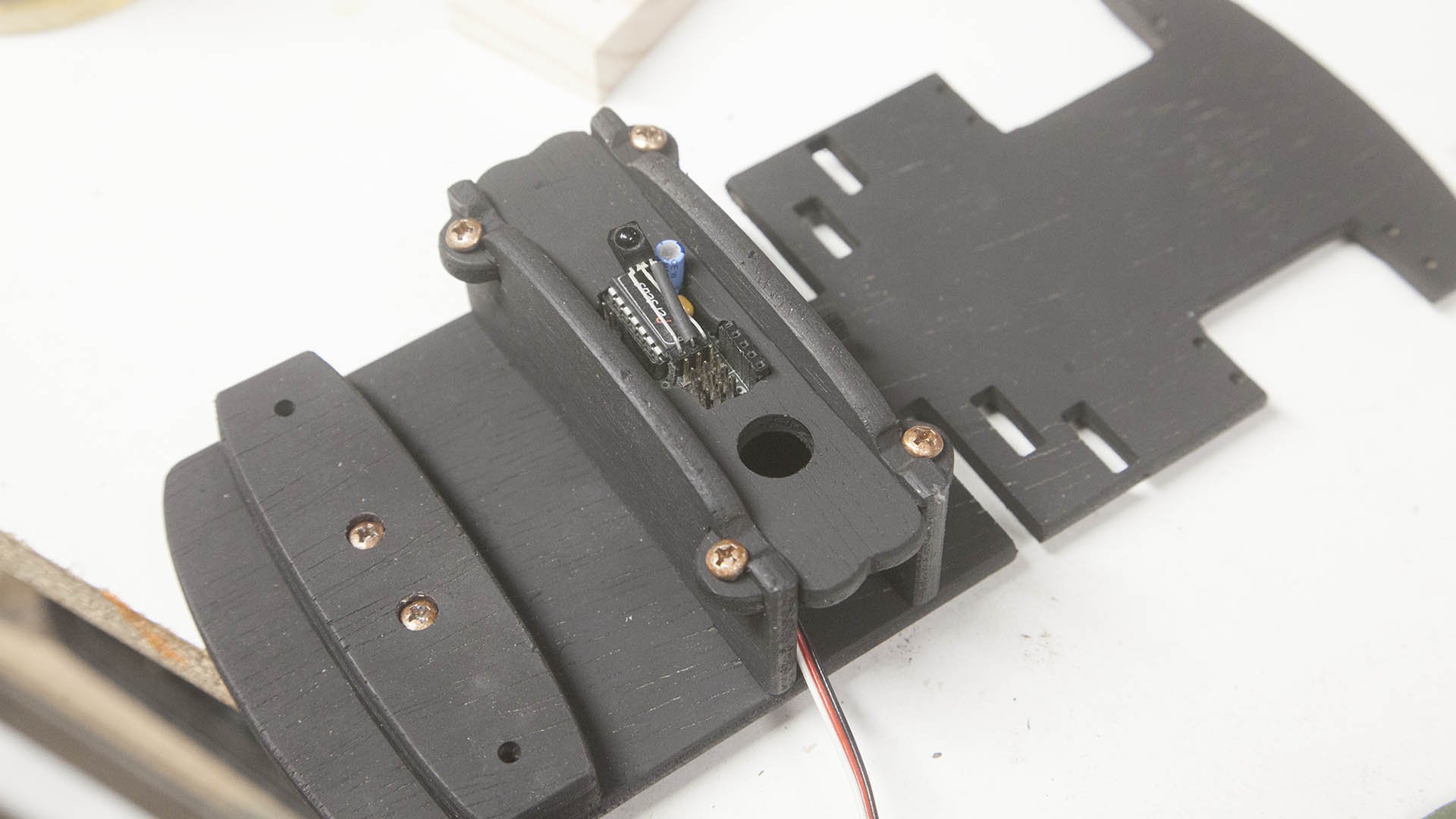
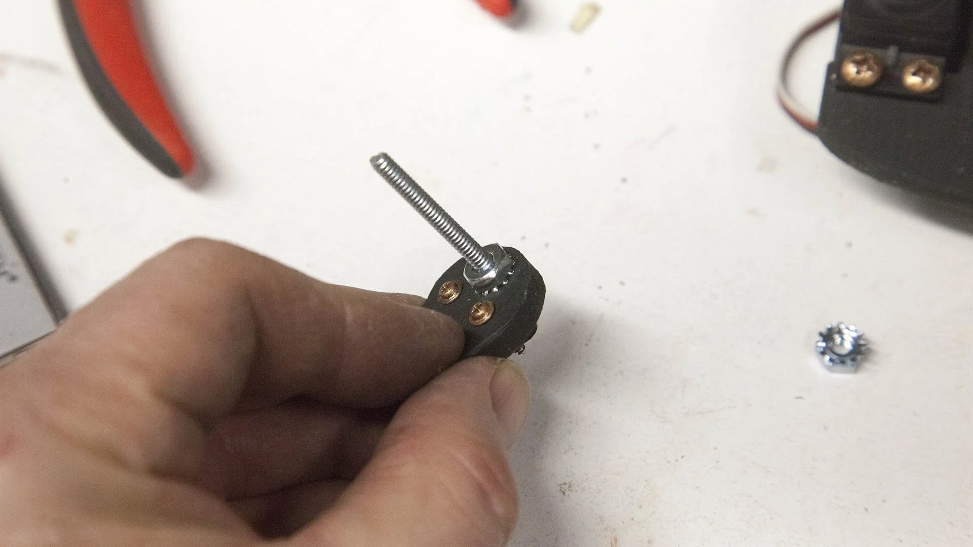
The third servo is mounted in the center with a cam connected.
The cam moves the two center legs. In the center position both legs are just off the ground.
In the left position, the left leg is pushed down raising the left front and rear legs off the ground.
In the right position, the right leg is pushed down raising the right front and rear legs off the ground.
When the legs on one side or the other is raised, this allows the legs to be positioned in a position that will allow them to move the walker once that side is again on the ground. By sequencing the legs this way, the walker can maintain various gates.
The servos are controlled with a very small microcontroller, with a IR receiver connected to allow me to control the walker.
The New Design
The new walker works the same way as the previous version with the following exceptions.
The parts were designed to be milled with a 1/16” end mill on a CNC.
The parts were designed to be made with 7/32 plywood
The parts were rounded for aesthetics.
The tabs were removed from the legs for aesthetics.
Making the Components
The parts were created in Corel Draw and loaded into Vcarve to create the toolpaths. I can cut all the components for one walker out of two 12” x 12” pieces of plywood.
Here, the CNC is cutting the base components.
Here, the CNC is cutting the Leg components.
Both sides are given a light sanding to remove any burs that are on the cuts.
The components are then removed from the stock. Note that each component is pushed from the top. Internal cutouts in a component are pushed from the bottom.
This keeps the tabs from blowing out a chunk of the component.
I remove the tabs and round over the edges slightly by using a 1/8” round over bit in my router table.
On any small pieces I use some flush cut snips to remove the tabs.
And finally, I use a fine sanding sponge to give the edges a light sanding.
The finished components.
Painting the Components
I five the base and the lower legs a coat of flat black paint.
The upper portion of the legs are given a flat green coat of paint.
Assembly
The following is may assembly process.


Update - 11/29/21 - Battery Holder Found
I decided on this 4 AA battery holder. It comes in a two pack and includes a switch.
Two holes were added to the plans so that 1/2” #6-32 machine screws could be inserted at the positions shown here. The screws are attached with the head sitting about 1/4” high. This will allow you to loop a rubber band around the screws.
The battery holder lead is routed through the hole in the center leg support. The battery holder is held in-place with a rubber band looped around the heads of the screws and used to hold it in place.
Two more holes were added to the plans near the rear to the front of the servo holder. These allow two 1” #6-32 machine screws to secure the switch.
One end of the switch is connected to the battery holder. The other is connected to the fourth servo position shown here. Note that the black lead faces the front of the bot, just like the servo connectors.
Parts
Battery Holder and Switch
Standard Size Servos
Amazon: Set of 4 Servos

Controller
IR Remote
Amazon: Sony IR Remote
Hardware
24, #6-32 X 3/8” Machine Screws
2, #6-32 x 1/2” Machine Screws
6, #6-32 x 1” Machine Screws
2, #6-32 x 3/4” Machine Screws
2, #6-32 x 1-1/4” Machine Screws
1, #6-32 x 1-1/2” Machine Screws
11/32” Plywood stock
2, 12” x 12”
Conclusion
Thats it, the walker is completed.
Note that the walker is powered up when the battery connector is plugged into a small header on the microcontroller board.
Update 11/29/21
A switch is now used to power up the walker.
I would like to provide links to the components, as well as making the plans available, but there is a little more work that needs to be done in order to do that.
First off, I need to model all the components so I can provide actual step by step instructions. Some of the components such as the battery holder I used is no longer available so I need to source something different.
In order to do the additional work needed, I need some feedback from you folks to see if there is any interest in this project. Please contact me via this web site if you are.
Video of the Process
A quick video showing the build and how the FirstWalker moves.