

The KRmc01 workbook, starts you off with a very simple electronics layout for the initial build.
In the upgrade workbooks we add even more connections.
As with my KRMx02 builds, I decided to move my KRmc01 electronics to a DIN rails system as well.
The system shown here is what I am currently using to control my KRmc01. Its gone through a few iterations, but this one
(for now) seems to be working out the best.
The Layout

The layout pretty much follows my other DIN rail layouts. In the case of the KRmc01 its almost identical to that of the KRMx02 DIN rail.
I go into more detail on the KRMx02 DIN rail here:
Lets take a closer look.
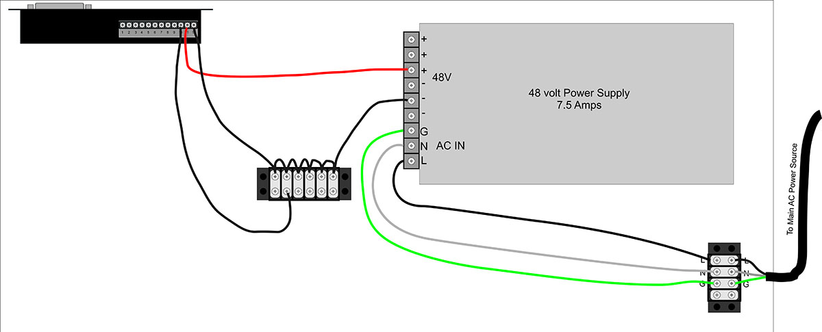
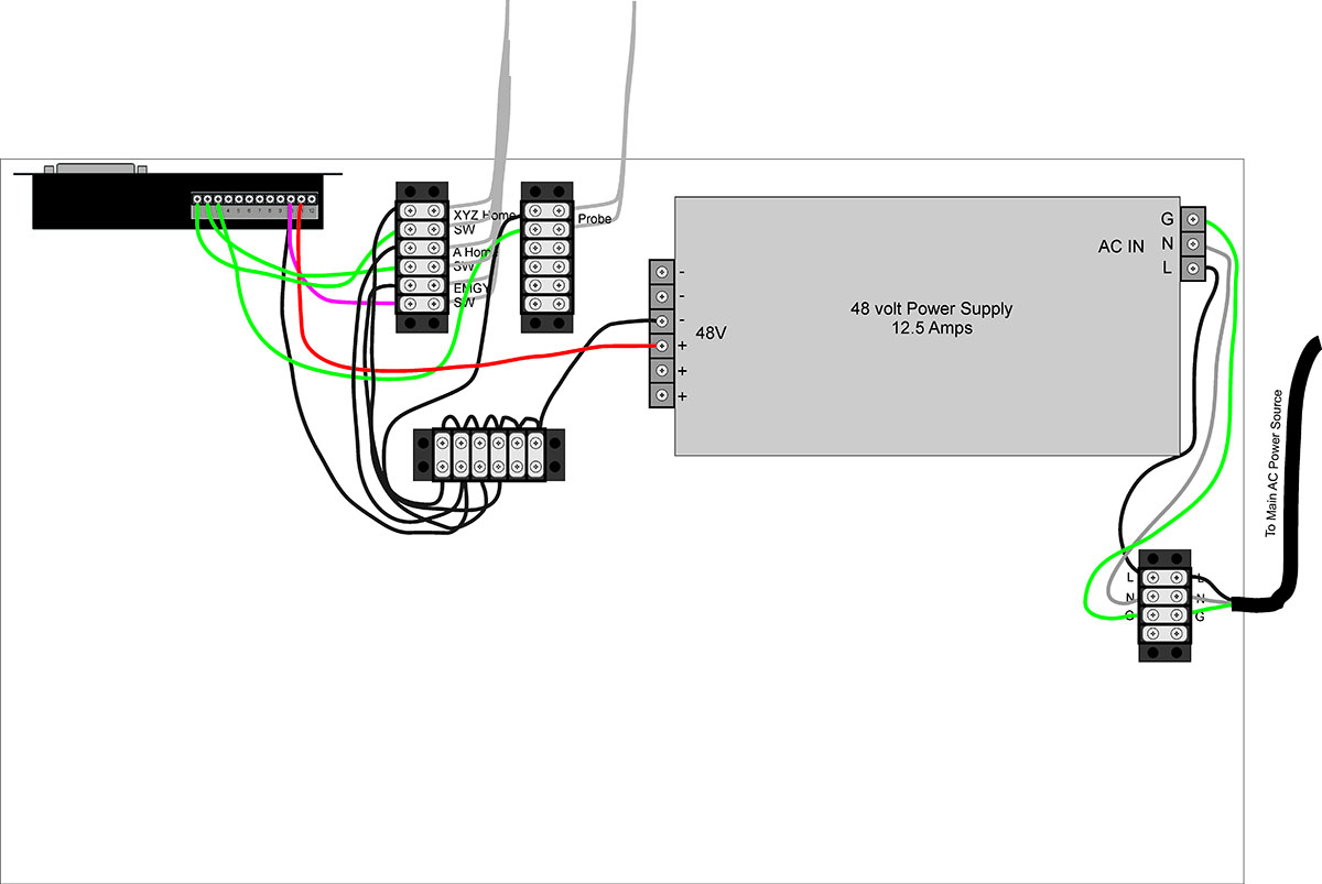
Power Distrobution
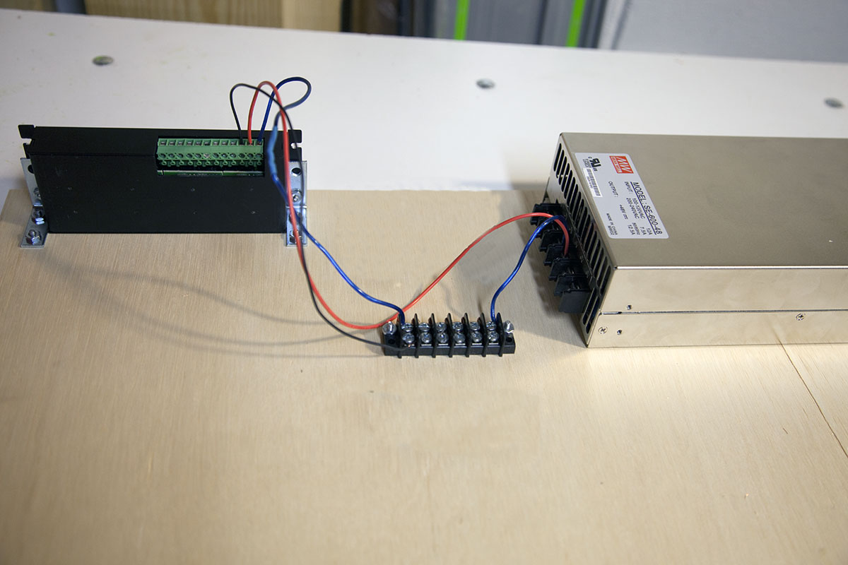
One thing I started to do differently was to mount an additional DIN rail to the top of the power supply.
This allows me to mount my power distributuin terminials and voltage converters without loosing any space on the main board.
Here is the 48v, 12v, and 5v termincal blocks. To the right is an AC - 5v & 12v power supply board.
I'm using the KRMx02 layout for the main AC power terminals and On/Off switch.
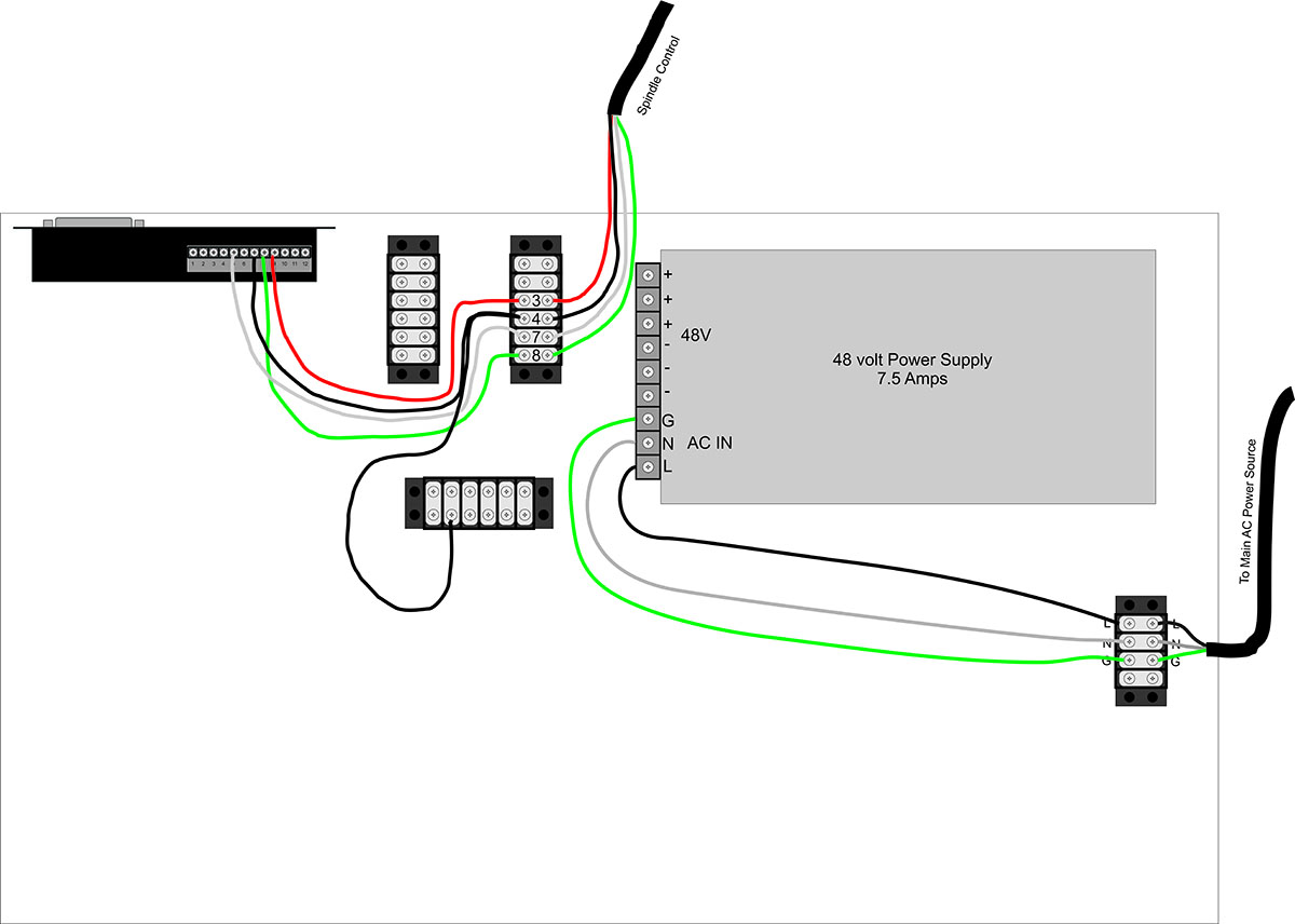
Spindle Control Terminal Block
To the left of the On/Off switch I mounted the spindle speed terminal block.
These wires directly respond to those in the Spindle Control workbook.
G540
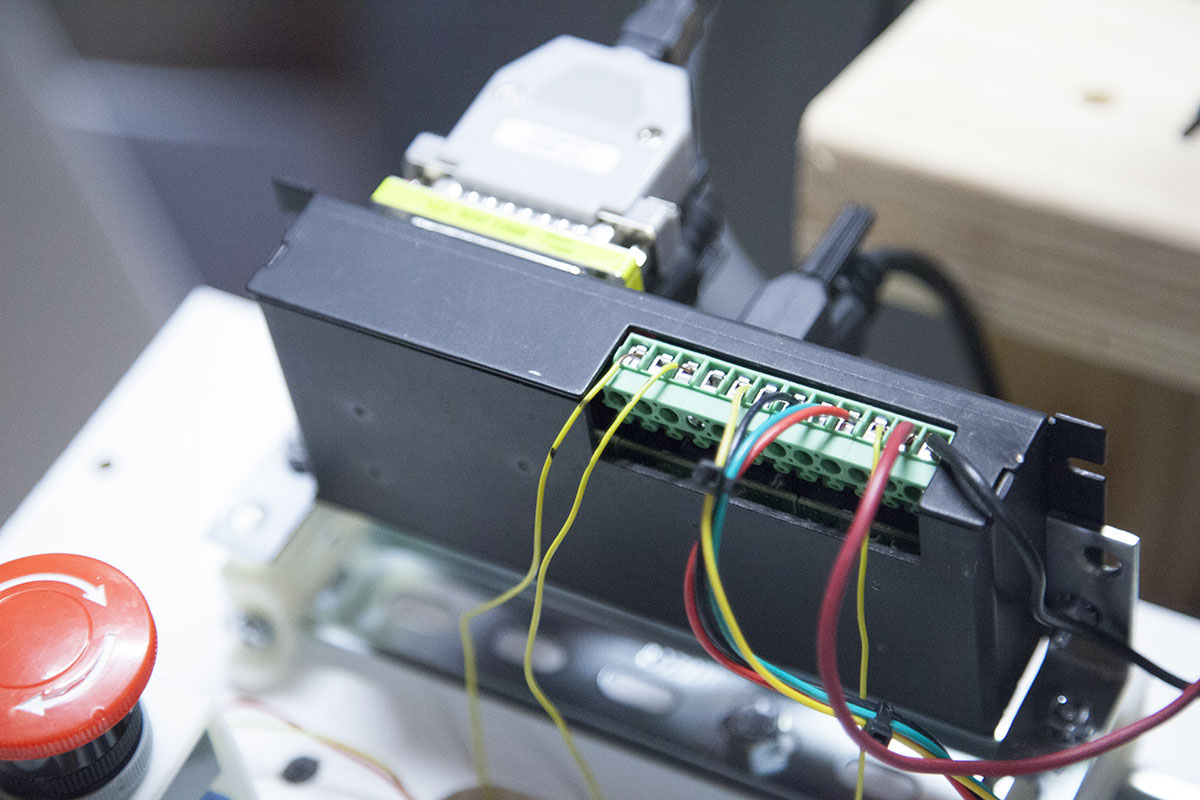
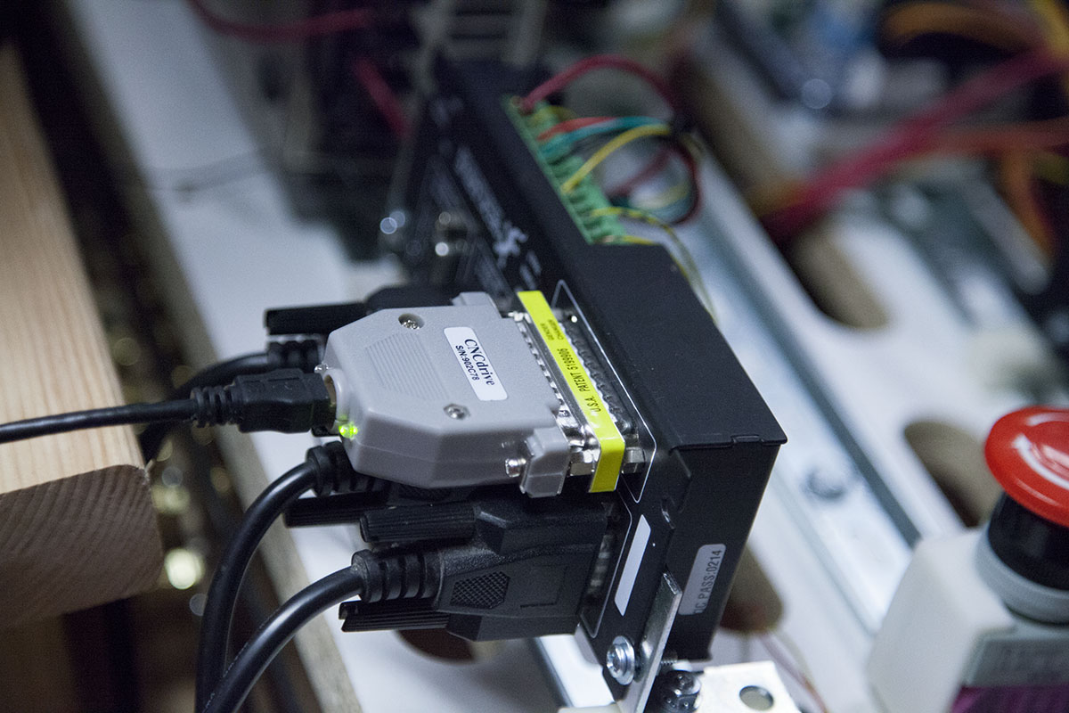
The G540 is also mounted exactly like G540 on the KRMx02.
Here its sporting a UC100 motion controller.
While I have an Estop mounted on the actual machine, I like to place an extra Estop on the DIN rail board. Here, you can see its located just in front of the G540.
Windows 7 PC
Just under the spindle terminal block and the On/Off switch is the mini ITX mother board that I am using to control the CNC mill.
It's mounted on 4 small DIN rail brackets.
The PC power supply and hard drive are mounted to the left of the mother board.
To make things a little more rugged, I will be replacing the mechanical hard drive with an SSD.
I've mounted a small make shift panel to the lower right of the mother board.
This gives me a conveniant place to control the mother board power.
Conclusion
While this is my current system, the DIN rail system will allow me to make quick changes as needed.
Also note that I could have taken the 12v and 5v supply from the PC power supply.
For now the DIN rail board is sitting on a small table in front of the mill. Eventually it will be moved to the side of the mill enclosure.
Update 3/29/2018
I mounted the DIN rail board on the side of my KRMx01 enclosure. This gets it up and out of the way, yet makes it accessable if needed.