

I was ready to test the new table and down draft on my CNC Construction Set plasma CNC and needed a simple project.
The motor on this small 10" desktop drill press bit the dust. I decided to replace it with a DC motor and controller I salvaged from an old scroll saw years ago.
I managed to mount the motor and turn a shaft adapter on my lathe, so the mechanical portions of the mod were complete. Now I just needed a nice box to hold the speed controller.
The current state of the plasma CNC is not ideal for a quality project. The build has the following issues that will effect the cut quality.
No Torch Height Controller
Cutting thin sheet metal can be very problematic as it tends to warp as you are cutting it. Even a slight amount of warping will effect cut quality and the amount of dross on those cuts. With a torch height controller the torch can actually follow the height of the stock in real time.
No Initial Height Sensor
I have to zero the torch to the stock manually. This is tedious and prone to error. In addition any warping will effect the pierce and cut quality. An initial height sensor will allow you to quickly find the correct height from the stock at the start of each cut.
No Thrust Bearings
I am using captured bearings to keep the helical couplers from moving. While this works there is a slight amount of backlash that can't be removed. By adding one or more thrust bearings this backlash can be removed completely.
Old Lead Nuts
I am using some very old and worn ACME nuts for the X and Y axis. These nuts have considerable backlash. I only keep them around for proof of concept experiments.
On Last Item of Note
This is my very first bent steel project box. I'm pretty sure its not going to be perfect. Knowing this, I'm only looking for basic functionality. I can always replace the box down the line as I get better at making them.
The Bent Steel Project box.
Lets take a look at the project box. Its a small that will house the controller board assembly. Its main porpose is to remove the exposure to the board and to give me some sort of mounting point to attach it to the drill press.
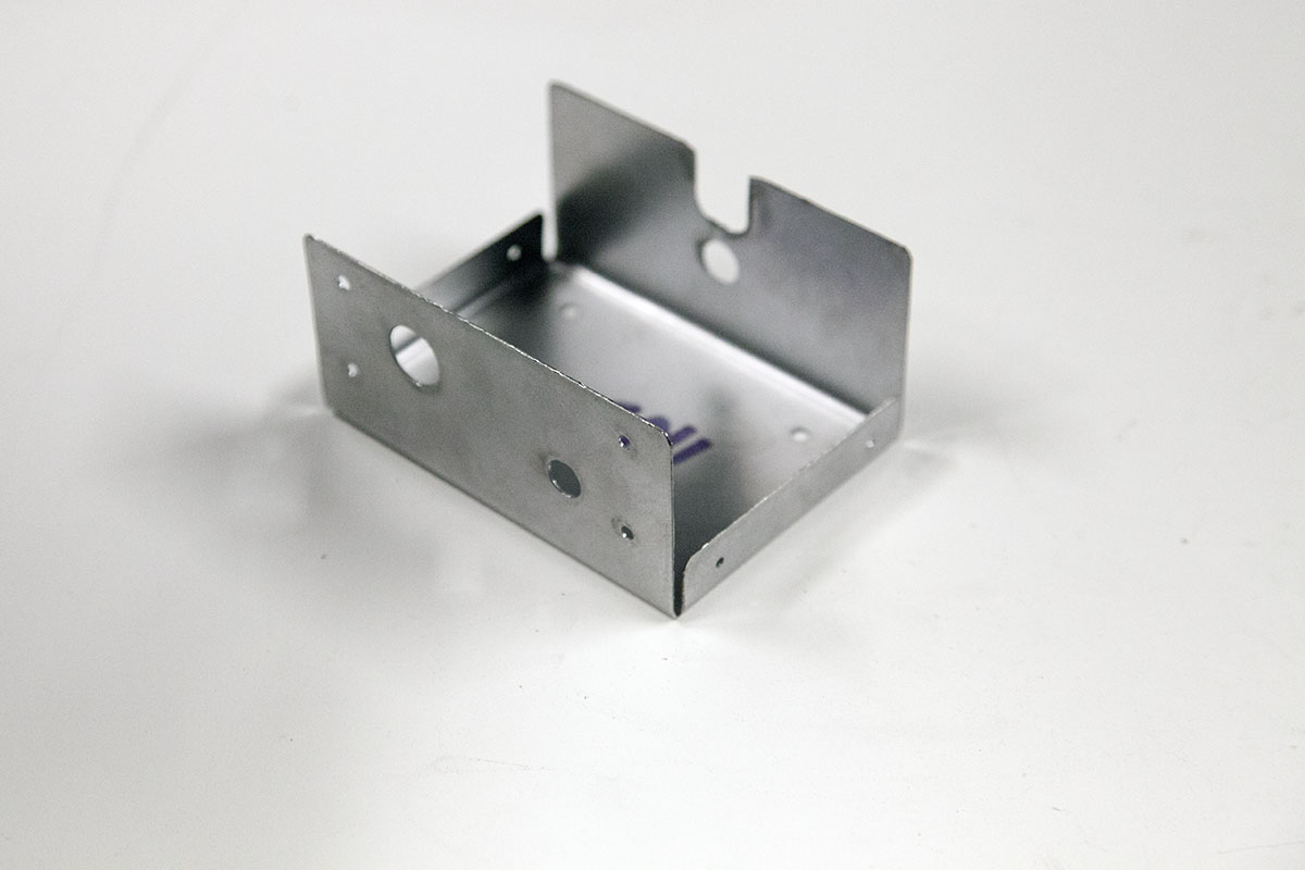
The project box has two components. The first shown here is the base. It is cut on the plasma CNC then bent into shape with my finger press.
The base is the meat of the project as this where all the components will be mounted.
The second component is the cover. It covers the base and is attached with 4, #4 sheet metal screws.
Both these components will be cut out of a sheet of 12" x 24" piece of 22 gauge steel.
Please note that I am going to be using a finger break (box break) to create these bends. If you don't have a finger break you will have to omit the side tabs and add some small angle brackets instead. This will allow you to use any of several methods to bend the sheet metal.
The Drawings
I started by laying out my base and cover in CorelDraw.
The inside of the enclosure will have the size of 4.5" wide x 3" deep x 2" tall. This is plenty enough room to house the small controller assembly.
Since this is my first bent project box, I am almost cetain I will have to go back and tweak some things.
Once I was satisfied with the design, I prepped the base and cover so that I could create some tool-paths in SheetCAM.
Basically, the prep consists of combining the shapes of the component profiles, and placing the pilot holes, cutouts, and main profile into separate layers.
The prepped parts were then exported as the following DXF files.
Small holes can be problematic when cutting on a plasma table. I created small pierce only pilot holes to be drilled out later.
CAM
I started new jobs in SheetCam and loaded each of the DXF files.
SheetCam kept my objects in their respective layers so creating tool-path operations very easy.
The operation for the pilot holes is actually a drilling operation using a plasma tool. This causes the plasma torch to do a pierce hole only.
Once the operations were complete, I saved the Gcode so that I could load them into Mach 3.
Making the Components
I loaded each file into Mach 3 and preceded to cut them with the CNC Construction Set plasma cutter.
I cut the base.
I cut the Cover
I used a flap sander to remove the dross from the cuts.
I drilled out each of the pilot holes to thier final sizes. I also sanded the whole surface with some 220 grit sand paper using a palm sander.
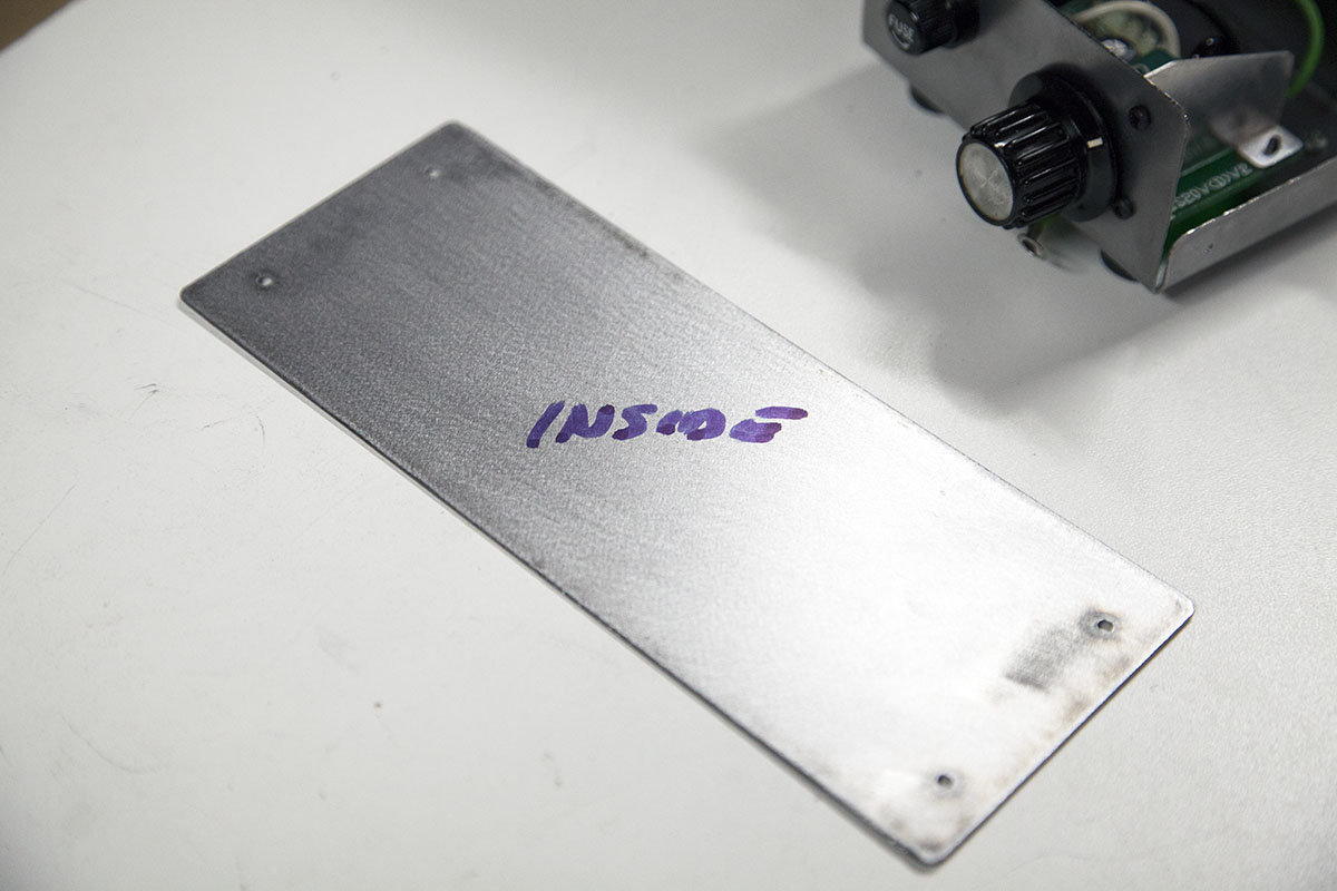
At this point you need to pick the best side and use it for the outside of the part, then mark the other side as the inside.
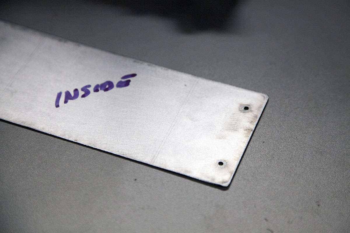
I marked the locations for the bends. The bends will be done on the inside.
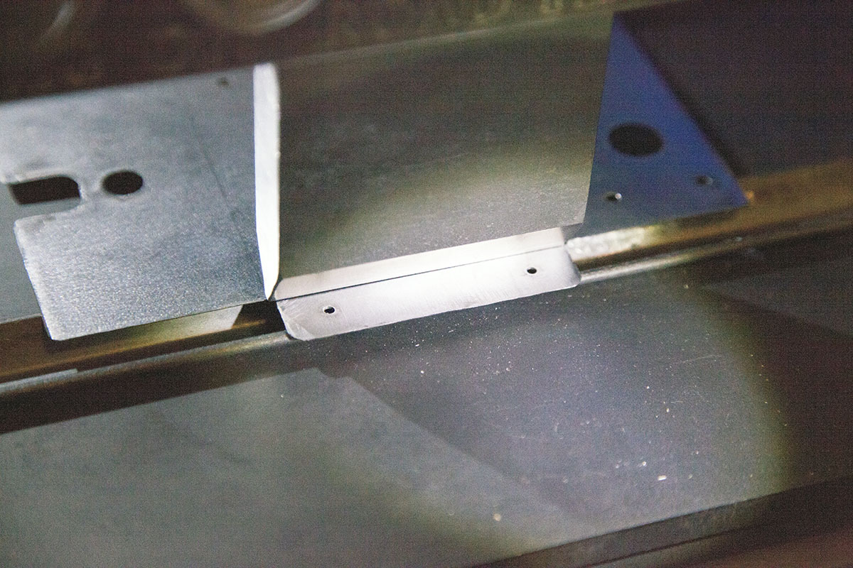
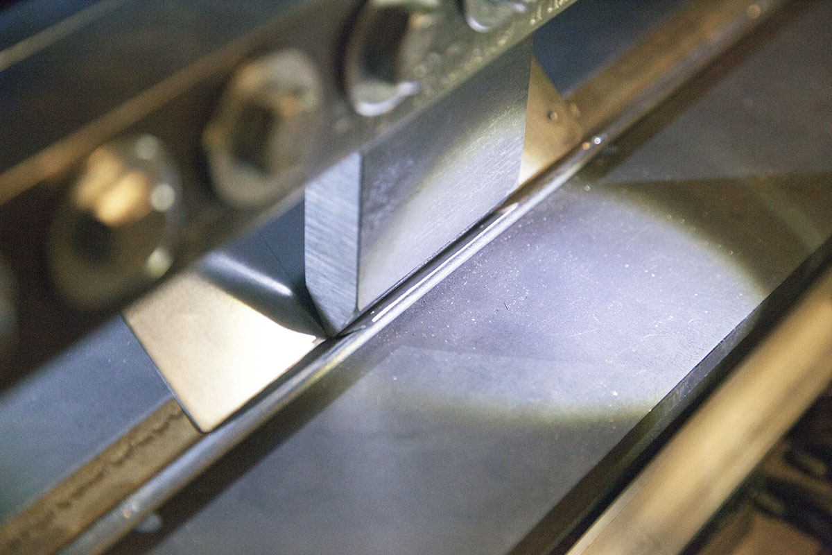
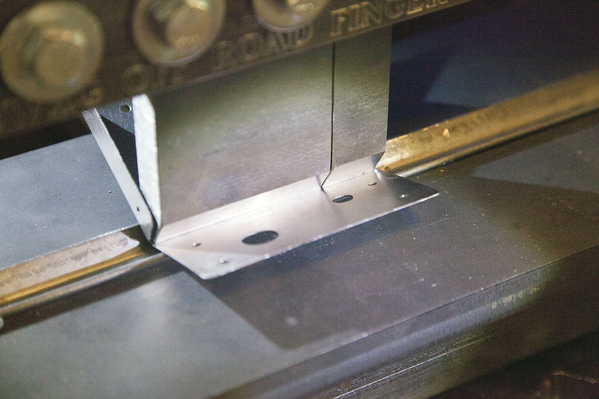
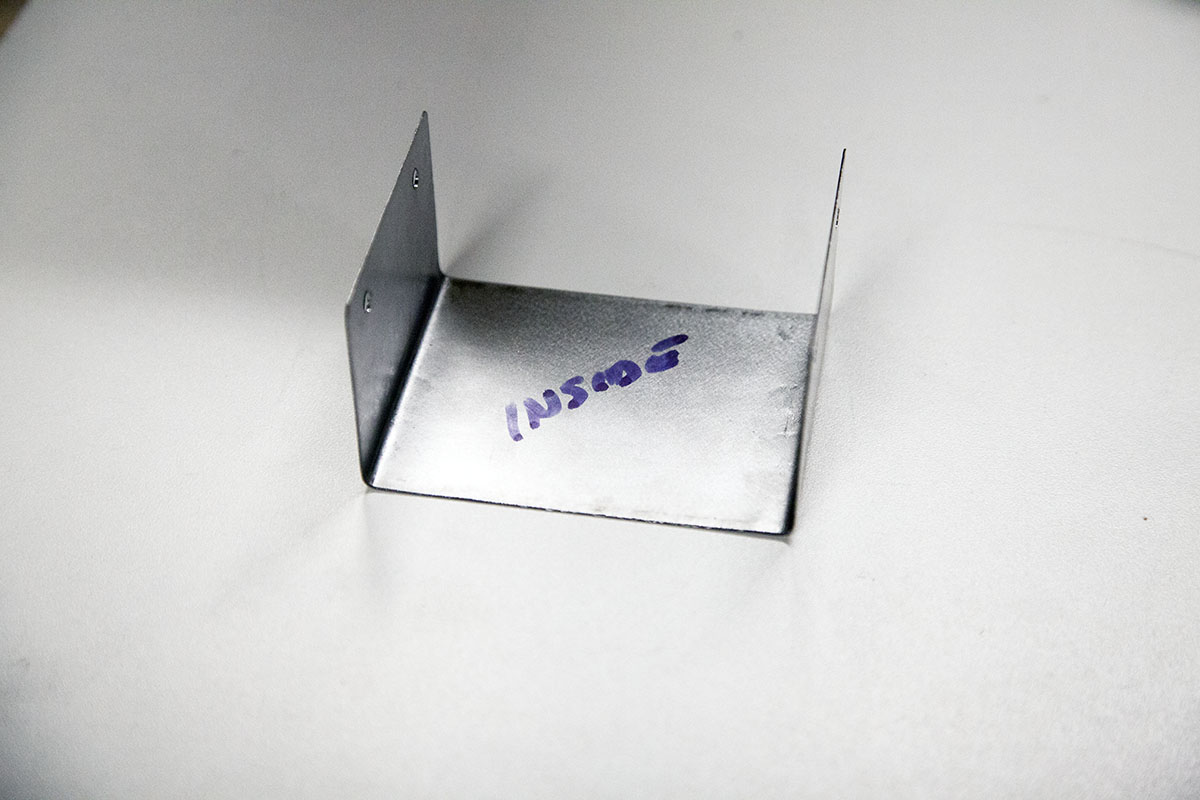
I bent the two side tabs first, then moved to the ends. Note that that I added two fingers to create a die that was just under the width to allow the two side tabs to clear the die.
This is the main reason for using a finger press.
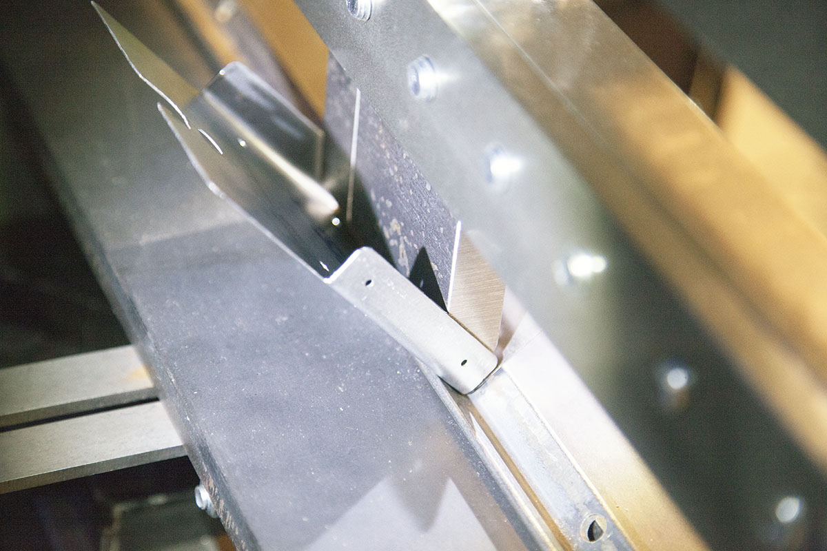
I repeated the process on the cover.
Notice the bend lines have two marks. My finger dies are pretty thick at the point. With the tip nearly 1/8" thick, I added a 1/16" offset. This allowed me to align the front of the die tip with the offset. By doing this the bend was centered on the orginal mark.
Assembly
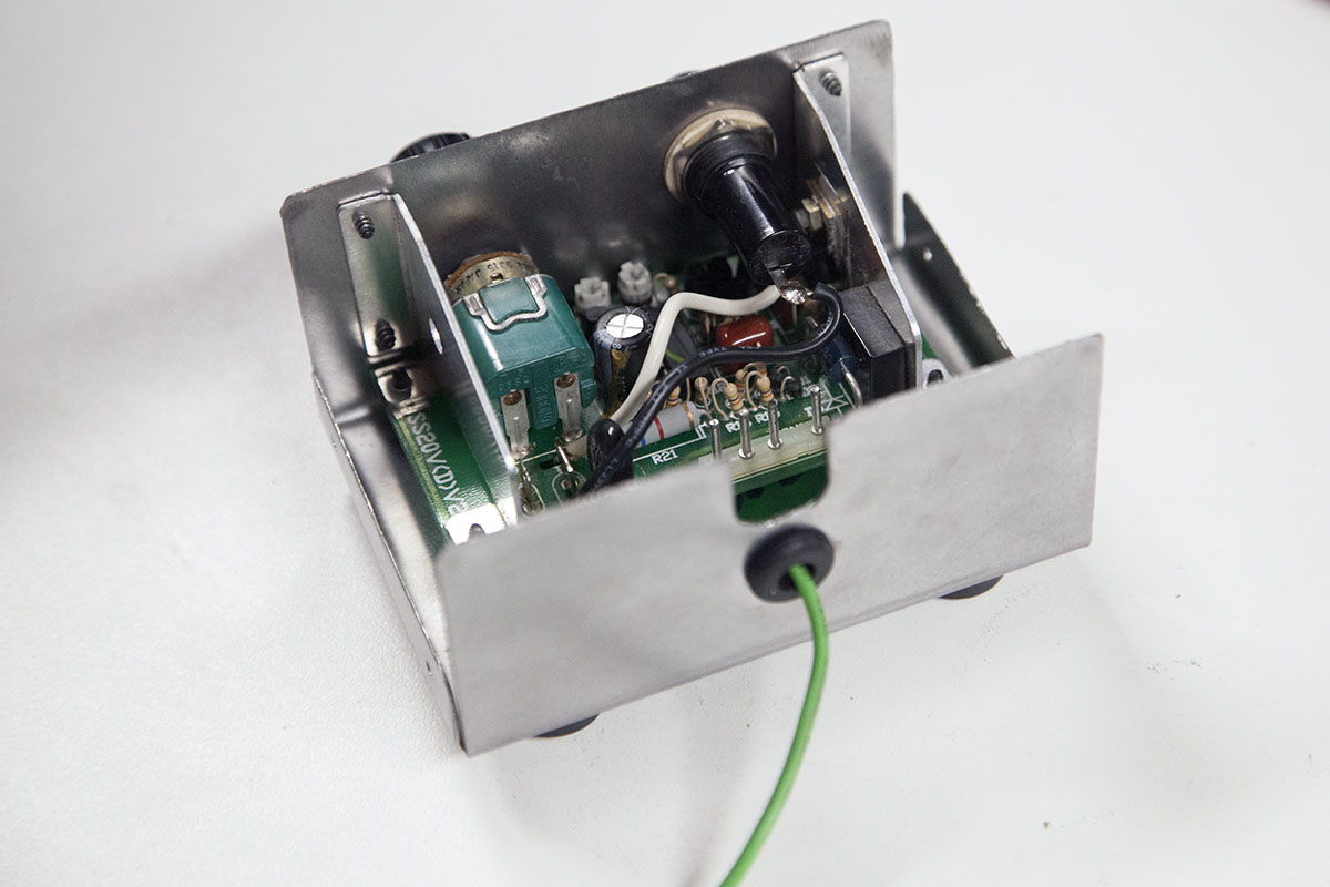
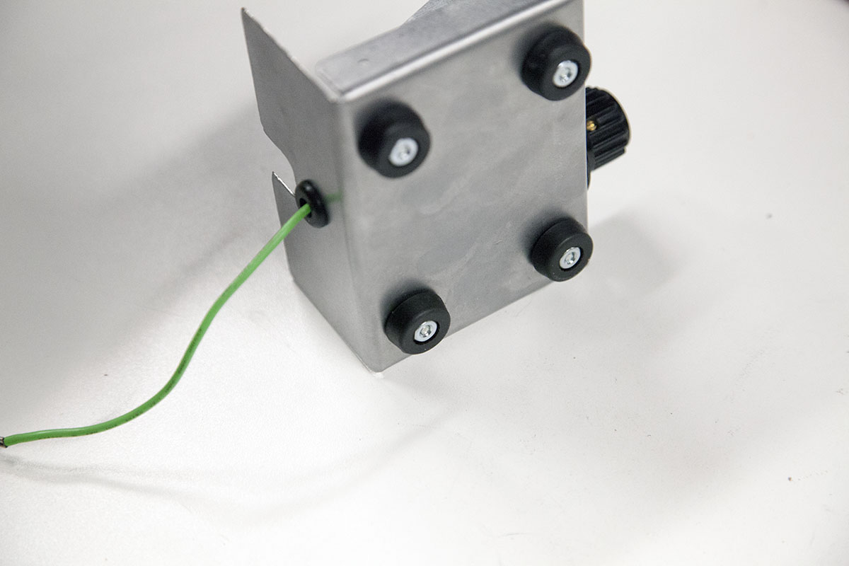
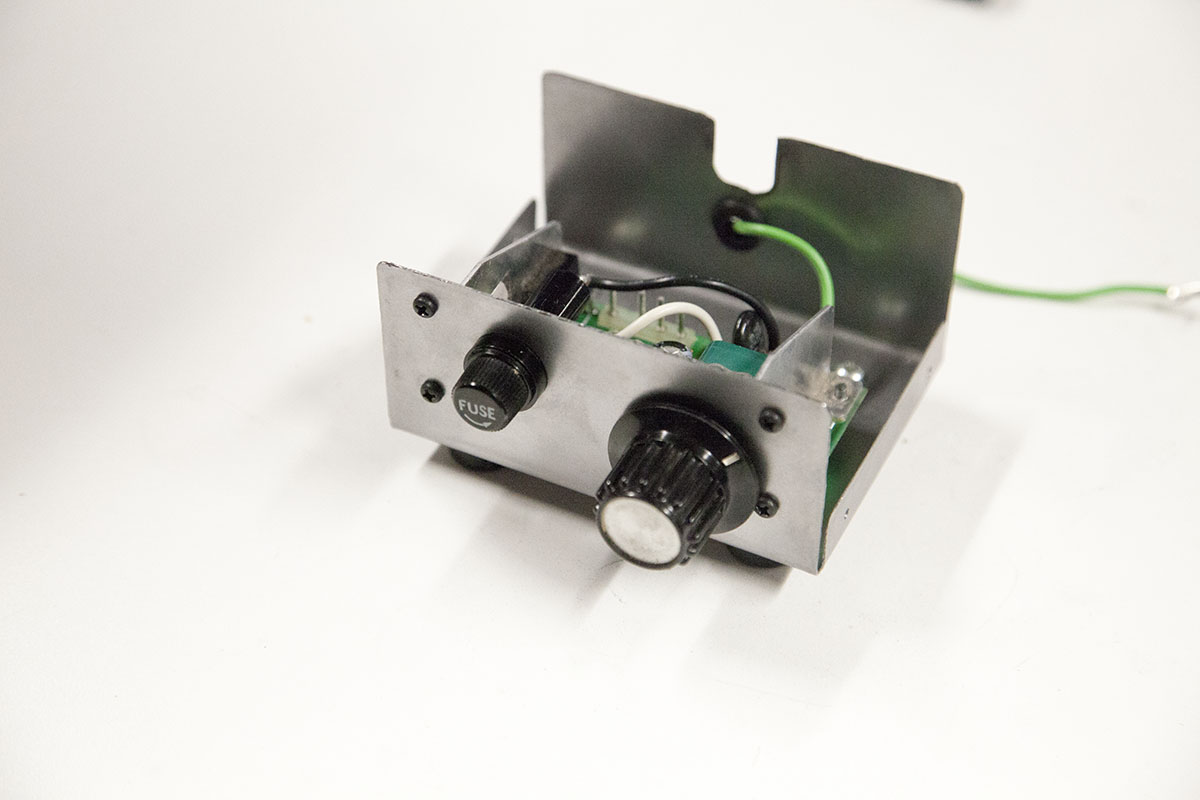
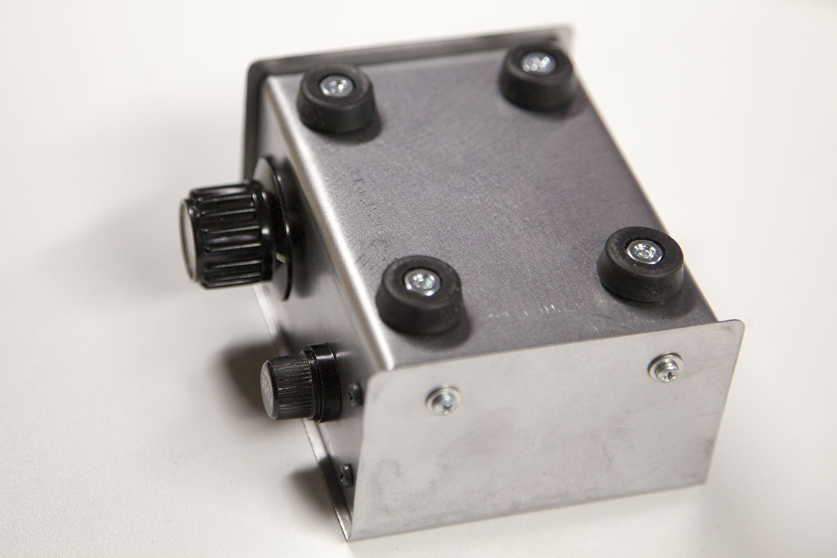
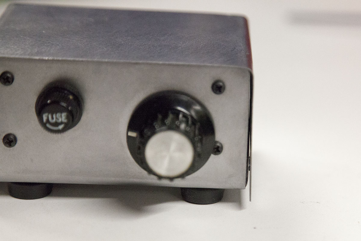
I added the feet, controller, and grommet to the base.
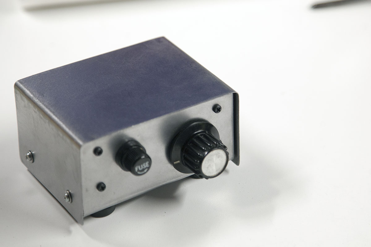
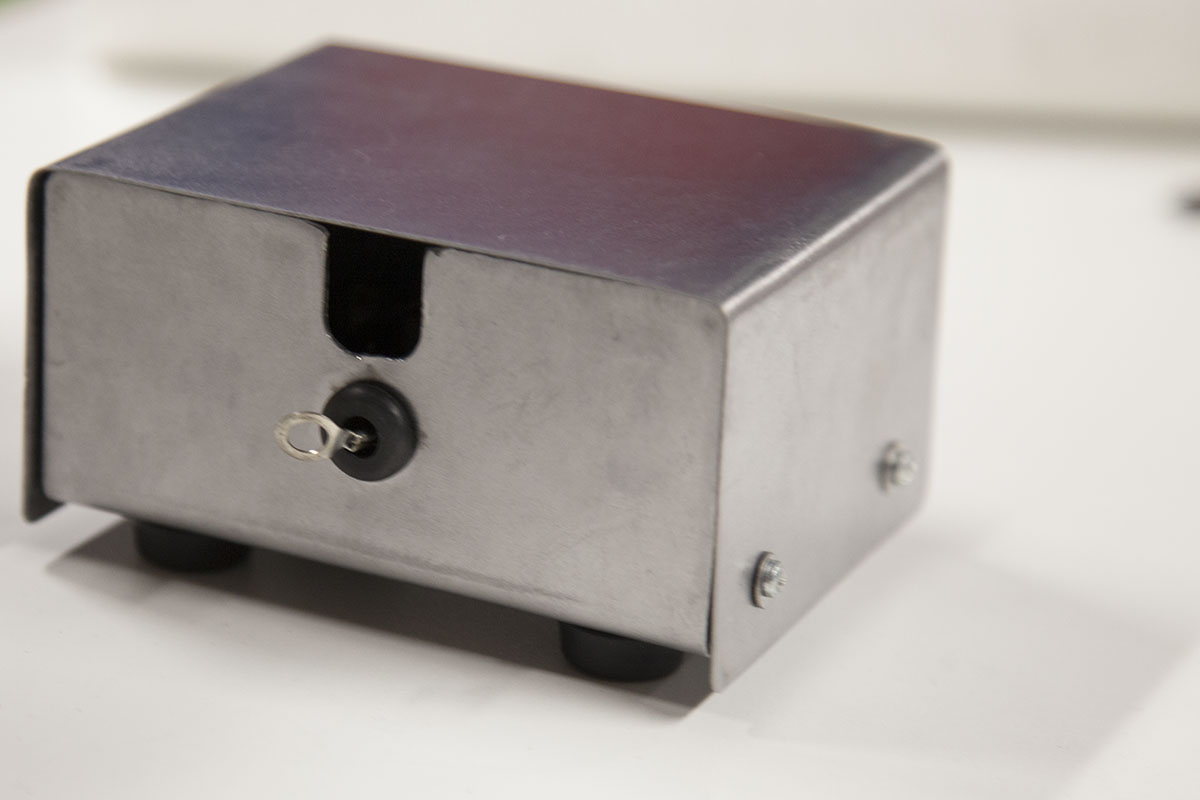
The cover was then added.
Conclusion
The build was not without some issues. The holes in the cover did not mate up with the holes in the side tabs. I actually had to enlarge the cover holes so that it would fit better.
This was no doubt due to me not taking the bend radius into account when calculating the offsets.
I went ahead and raised the cover holes about .05" on the cover so if I decide to make the part again they will line up.
I think on my next box, I will leave out the tab holes and drill them after the cover is formed. This way I can use the cover holes to mark the holes in the tabs.
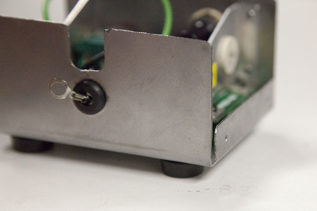
In addition the side tabs on the base stuck out enough to keep the cover from resting against the edges of the front and rear faces.
This could be corrected by using the correct sized finger on the side tabs. I will probably need to add a small groove when cutting the profile to allow the tabs to be bent so that the outside of the tab is flush with the edges of the front and rear faces.
All in all, I am very satisfied with this first box, and wont worry about the corrections needed until, I create my next project box.
I have the replacement ACME nuts and thrust bearings, and will be replacing them soon. I also have a THC on the way. These will help with the cuts, and with some design changes my next bent steel project box should be much better.
With the box complete, I attach the motor and power cables.
The box is then mounted to the side of the drill press with a powerfull magnet.
The power cable is passed up through the bottom of the head.
Here is a video I made of the cutting and some of the bending of this project.
One Last Thing
After completing this project and making the video, I realized the work clamp was not connected to the plasma cutter. All these cuts were made with the initial starting arc. This drastically affects the plasma power and its focal point. Had I had the ARC Start signal hooked up to the system, Mach3 would have detected this.