

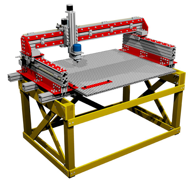
There are advantage to using a wood stand for your KRMx02 CNC. They are easy to build using basic tools, and have the advantage of damping noise and vibration if built correctly. The same design is used for all the build sizes. You just change the size of a few of the components for each size. The 50" x 102" build utilizes two 50" x 50" stands.

Components
The following are a list of the various components along with the hole layout. Drill only the holes shown in the layout drawings. The others will be done later during assembly.

Posts
The posts are the same for all build sizes. They are 3" x 3" x 34". If you don't have access to 3" stock you can glue up four pieces of 3/4" boards. For the strongest posts you can glue up four pieces of birch plywood. Baltic birch is recommended.
Post Top Layout - All Holes are 3/8"
Post Bottom Layout - All Holes are 3/8"
Post Quantity and Sizes
30" x 27" = 4 posts at 3" x 3" x 34"
50" x 27" = 4 posts at 3" x 3" x 34"
50" x 50" = 4 posts at 3" x 3" x 34"
50" x 102" = 8 posts at 3" x 3" x 34"
Main Beams
The main beams are connected to the posts and form the sides of the stand. The upper main beam is what supports the weight of the CNC. They should be made from quality 3/4" plywood. At the very least cabinet grade birch, but Baltic birch is recommended.
!! Failure to make the main beams out of 6" x 3/4" cabinet grade plywood could result in the stands failure to hold the weight of your CNC, and could cause personal injury.

Main Beam Top Layout - All holes are 3/8". The hole layout of the holes is the same on both sides.
Main Beam Bottom Layout - All holes are 3/8". The hole layout of the holes is the same on both sides.
Main Beam Top Quantity and Sizes
30" x 27" = 4 beams at 6" x 43" x 3/4"
50" x 27" = 4 beams at 6" x 43" x 3/4"
50" x 50" = 4 beams at 6" x 66" x 3/4"
50" x 102" = 8 beams at 6" x 66" x 3/4"
Main Beam Bottom Quantity and Sizes
30" x 27" = 4 beams at 3" x 43" x 3/4"
50" x 27" = 4 beams at 3" x 43" x 3/4"
50" x 50" = 4 beams at 3" x 66" x 3/4"
50" x 102" = 8 beams at 3" x 66" x 3/4"
Stretchers
The stretchers are used to connect the two sides together. They can be made from hardwood, softwood or any kind of ply. Note that the layout of the holes is the same for both sides of the stretcher. All holes are 3/8"

Stretcher Layout - All holes are 3/8". The hole layout of the holes is the same on both sides.
Stretcher Quantity and Sizes
30" x 27" = 4 stretchers at 3" x 48" x 3/4"
50" x 27" = 4 stretchers at 3" x 68" x 3/4"
50" x 50" = 4 stretchers at 3" x 68" x 3/4"
50" x 102" = 8 stretchers at 3" x 68" x 3/4"
Cross Braces
Cross braces are attached to the stretchers and main beams. They are used to stiffen the stand. They can be made from hardwood, softwood, or ply. You wont drill the holes in the cross braces until later.

Cross Braces Quantity and Sizes
30" x 27" = 6 braces at 3" x 43" x 3/4"
50" x 27" = 6 braces at 3" x 43" x 3/4"
50" x 50" = 6 braces at 3" x 43" x 3/4"
50" x 102" = 12 braces at 3" x 43" x 3/4"
Hardware
The hardware consists of 5/16-18 carriage bolts of various sizes.

30" x 27", 50" x 27", and 50" x 50" Builds
Carriage Bolts
12, 5/16-18 x 2"
16, 5/16-18 x 4"
32, 5/16-18 x 5"
Hex Nuts
60, 5/16"
Washers
60, 5/16"
Lock Washers
60, 5/16"
50" x 102" Build
Carriage Bolts
24, 5/16-18 x 2"
16, 5/16-18 x 4"
80, 5/16-18 x 5"
Hex Nuts
120, 5/16"
Washers
120, 5/16"
Lock Washers
120, 5/16"
Construction
Once all the components for your stand have been cut and the holes drilled, it's time for some assembly.
Step 1
Using the 5/16-18 x 5" carriage bolts, washers, lock washers and hex nuts, attach the main beam components to the posts as shown here. Finger tighten only.

Step 2
To attach the cross braces you need to drill holes in the beams and the braces. The easiest way to do this is to clamp the brace and in place and use a portable drill and a 5/16" drill bit to drill a hole through both at once. Placement of the brace and the hole is not critical.
Using the 5/16-18 x 2" carriage bolts, washers, lock washers and hex nuts, attach a cross brace to each side of the beams. Finger tighten only.

Step 3
Square up the leg then tighten all the bolts. The top beams should be flush with the posts. Repeat the entire process on the second leg. Note that you will need four legs for the larger 50" x 102" build.

Step 4
Attach the four stretchers to the legs as shown here. Use the 5/16-18 x 5" carriage bolts, washers, lock washers, and hex nuts. Finger tighten only.

Step 5
Attach two cross braces to the rear stretchers. Place them on opposite sides of the stretchers. Temporarily hold them in place with clamps and drill 5/16" holes. Use the 5/16-18 x 2" carriage bolts, washers, lock washers, and hex nuts to complete the assembly. Finger tighten.

Conclusion
Ensure that the legs are plumb, and that the stand is square, then tighten the stretcher and cross brace bolts. Locate the stand where you plan on using the CNC and level it by using wood shims under the posts.
The 50" x 102" build will require two of these assemblies. Place them next to each other front to back, then level them.

Note that I left the front of the stand free of cross braces so that I could place a shop vacuum in side the stand. By bracing the front of the stand as well you will add rigidity to the stand.
Machine Examples

30" x 27"
50" x 27"

50" x 50"

50" x 102"