

In this article, we will install the components and do the final wiring.
Note that you can click on the images to enlarge.
Step 1 - Install the PID
Insert the PID into the cutout on the front of the enclosure. Do this by first slipping the wires through the cutout.
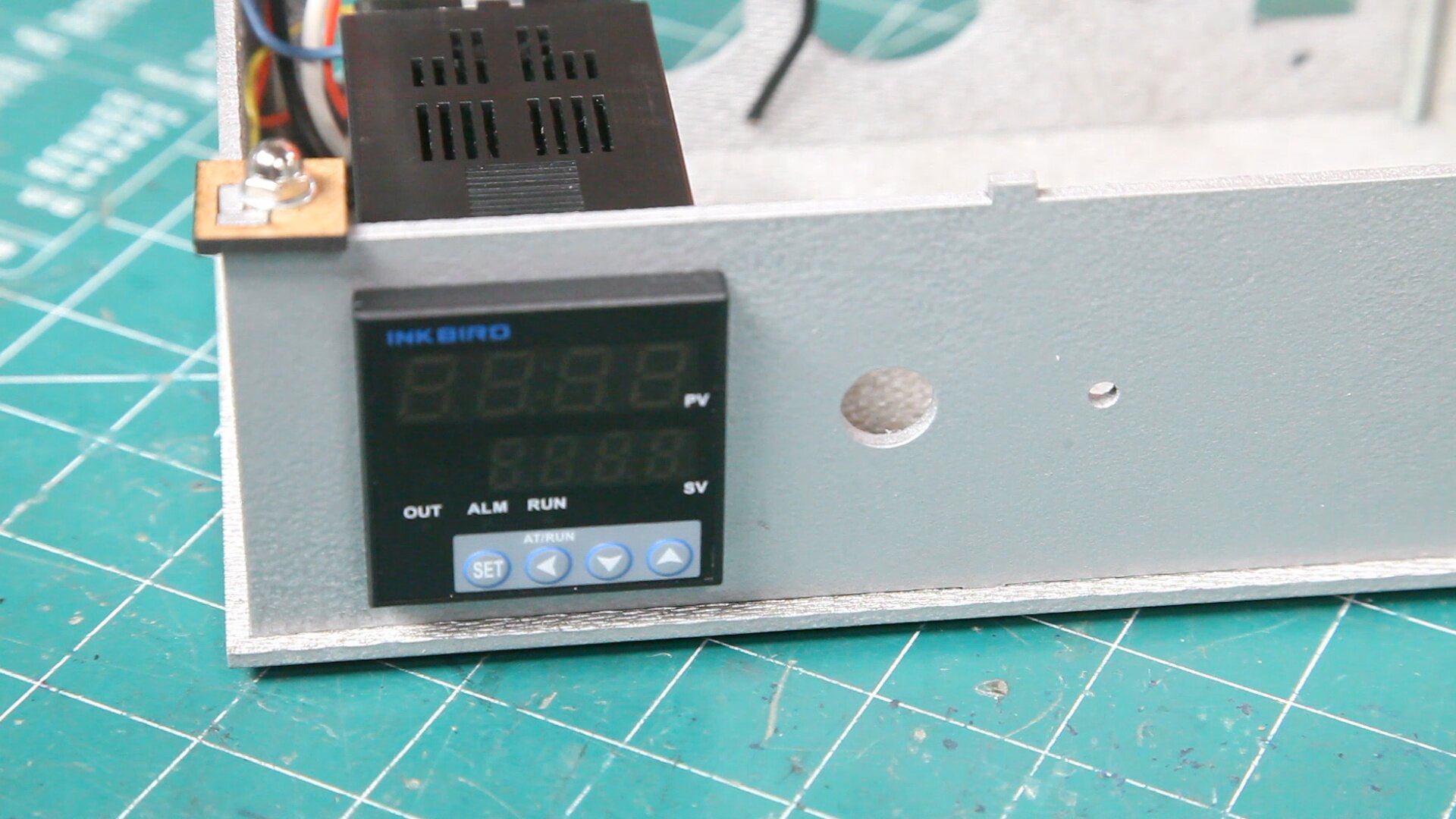

Make sure you will orient the PID so that it matches the orientation of your enclosure.
The first is for horizontal orientation and the second is for vertical.


Put the wires through the bracket and slip it over the end of the PID. Notice the orientation of the bracket with screw heads facing you.


Slide the bracket towards the panel to secure the PID.
Snug the PID by tightening the two screws on the bracket.
Do Not Over Tighten
Step 2 - Install the SSR
Start by installing a #6-32 x 1/2” into the hole closest to the side. Add a #6-32 hex nut.
Leave the nut loose as you will be slipping the heat-sink mounting tab under this nut.
Slide the SSR heat-sink under the nut.
Option
Note that you may want to attach the PID black wire before securing the SSR. See the option in Step 3.
Secure the other end with a #6-32 x 1/2” machine screw and nut.
Step 3 - Attach Black Wire
Strip about 1/2” of the insulation on the black wire (power) that is connected to the PID terminal 10.
Connect it to terminal 2(AC) on the SSR. Note that there is already a wire on this terminal, so this can be a little tricky.
Option
You can perform this step easier by connecting the wire before you secure the SSR to the enclosure
Step 4 - Install Switch
Strip about 3/4” of the insulation from the black wire connected to terminal 2 of the SSR and connect it to one of the end terminals on the switch.
Connector Option
If you have ring connectors, you can connect one to the end of the black wire attached to terminal 2 on the SSR.
You can then attach the ring connector to the switch as shown.
Notice the orientation. You want the end terminal to be facing the SSR and the center terminal up. This so you can access still access the center terminal after the switch is installed.
Insert the switch into the hole next to the PID and secure with the included nut.
Step 5 - Install the AC-In Connector
Install the pre-wired AC input connector and secure with two #6-32 x 1/2” machine screws and hex nuts.
I found it difficult to secure the bottom nut on the connector, so I removed the screws holding the SSR and moved it out of the way.
Once the connector was secured, I secured the SSR once again.
Important
Keep an eye on your connected wires when moving components. You don’t want them pulling out.
Step 6 - Install the Fuse Holder


Remove the nut from the fuse holder and slip the wires through the holes next to the AC connector.
Secure with the nut.
Step 7 - Connect Fuse
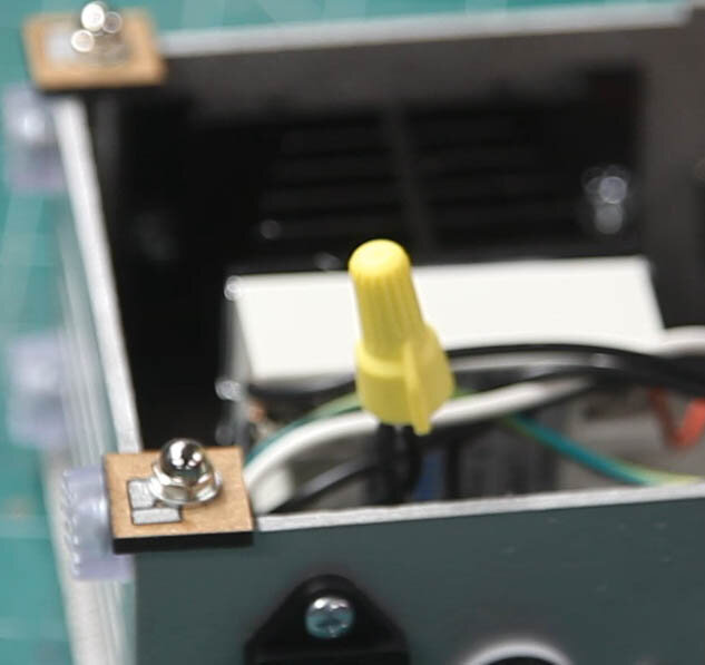
Using the short black wire from the fuse holder and the black wire from the AC connector:
Strip about 3/4” of the insulation from the wires and twist them together.
Attach a twist-on connector to secure the wires.
Connector Option
If you are using the quick connectors, simply plug the short wire with the female spade connector on the AC input terminal shown here.
Step 8 - Connect to Switch


Strip about 3/4” of the insulation from the long black wire connected to the end of the fuse holder.
Connect this wire to the center terminal on the switch.
Connector Option
If you are using quick connectors, connect the ring connector on the long black wire from the fuse holder to the center terminal on the switch. Or, as in this case to one of the end connectors on a two terminal switch.
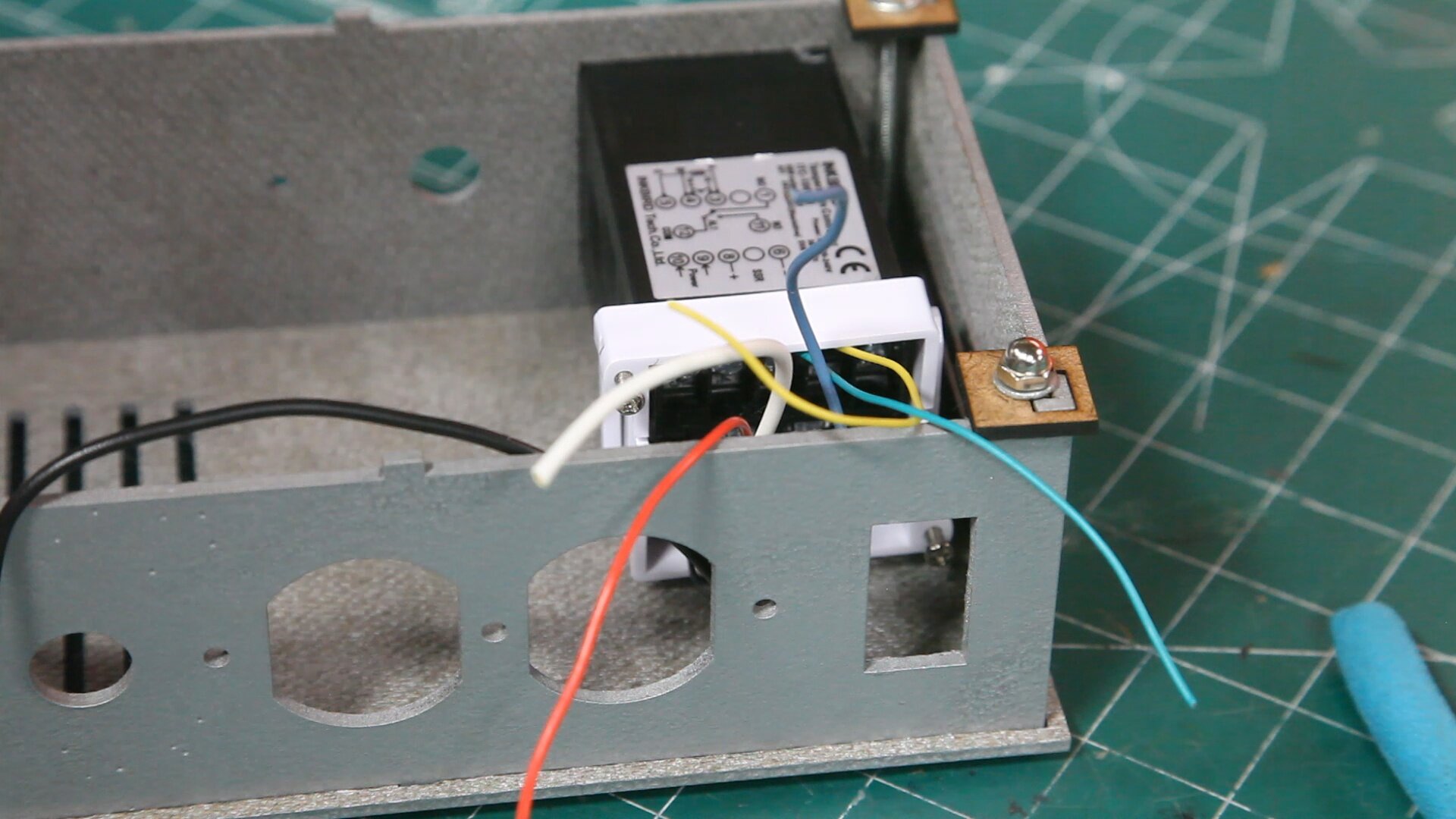
Step 9 - Connect the SSR Control Wires
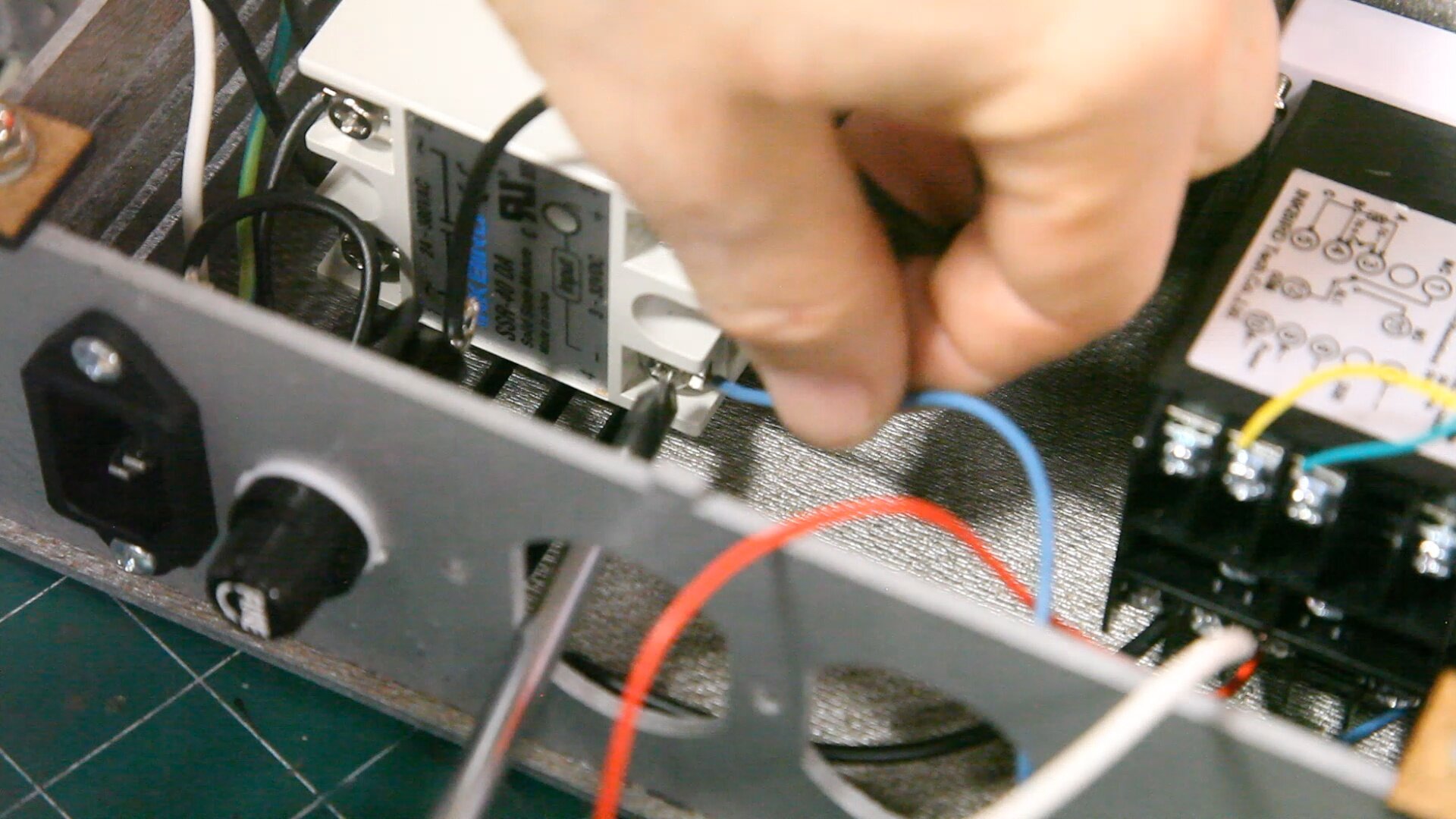


Strip about 1/2” of the insulation from the blue wire (SSR -) connected to terminal 6 on the PID. Connect this wire to terminal 4 (input -) on the SSR.
Strip about 1/2” of the insulation from the red wire (SSR +) connected to terminal 8 on the PID. Connect this wire to terminal 3 (input +) on the SSR.
Note that you can access the SSR terminals through the receptacle cutout in the rear panel.
Step 10 - Install Receptacle

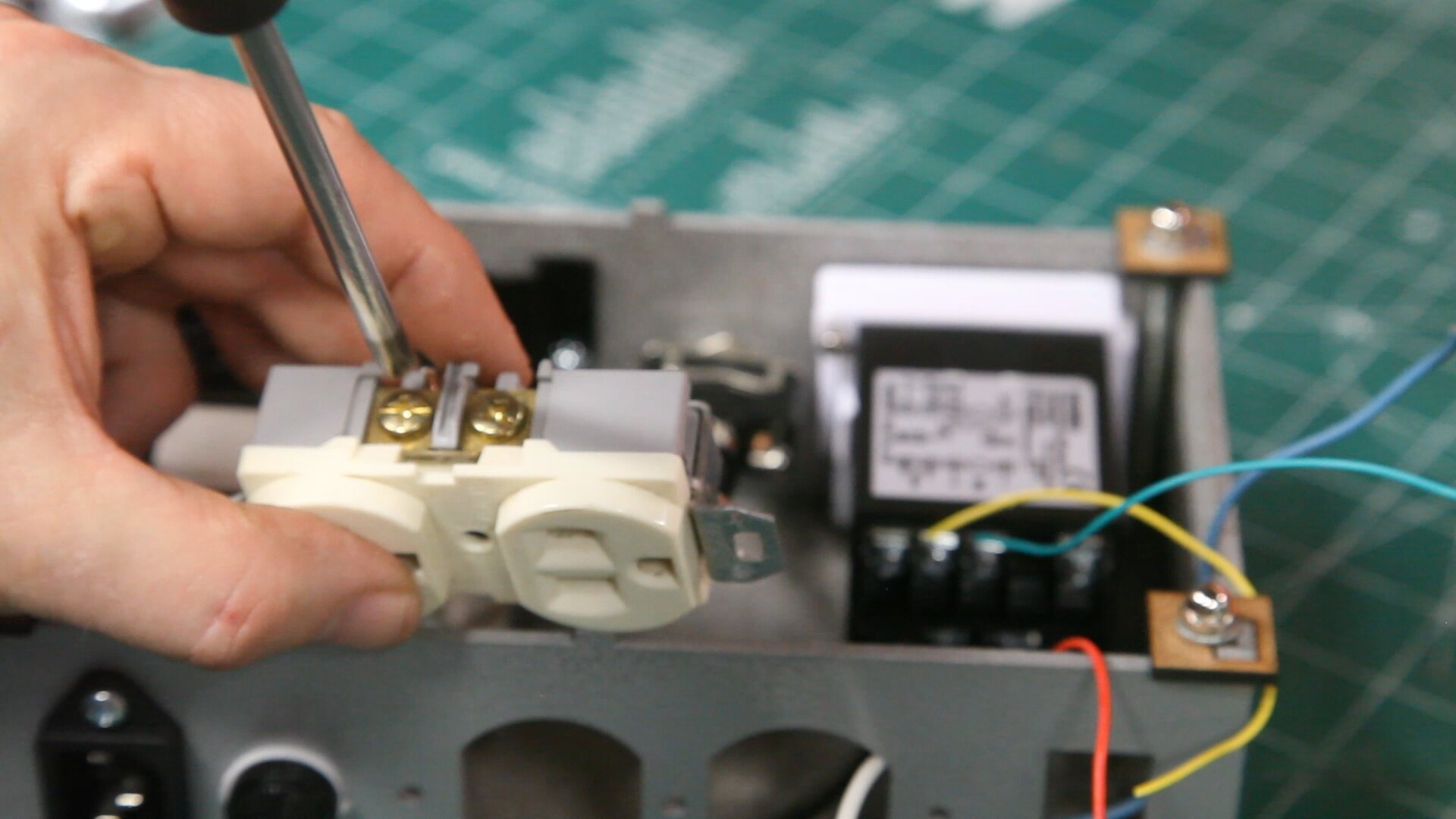

Strip about 3/4” of the insulation from the black wire coming from terminal 1(AC) of the SSR.
Connect this wire to the line side (smaller plug slot) of the receptacle.
Flip the receptacle over so that the line side is facing down. This is to give you access to the neutral side of the receptacle.
Install the receptacle into the cutout and secure with two #6-32 x 1/2” machine screws and hex nuts.
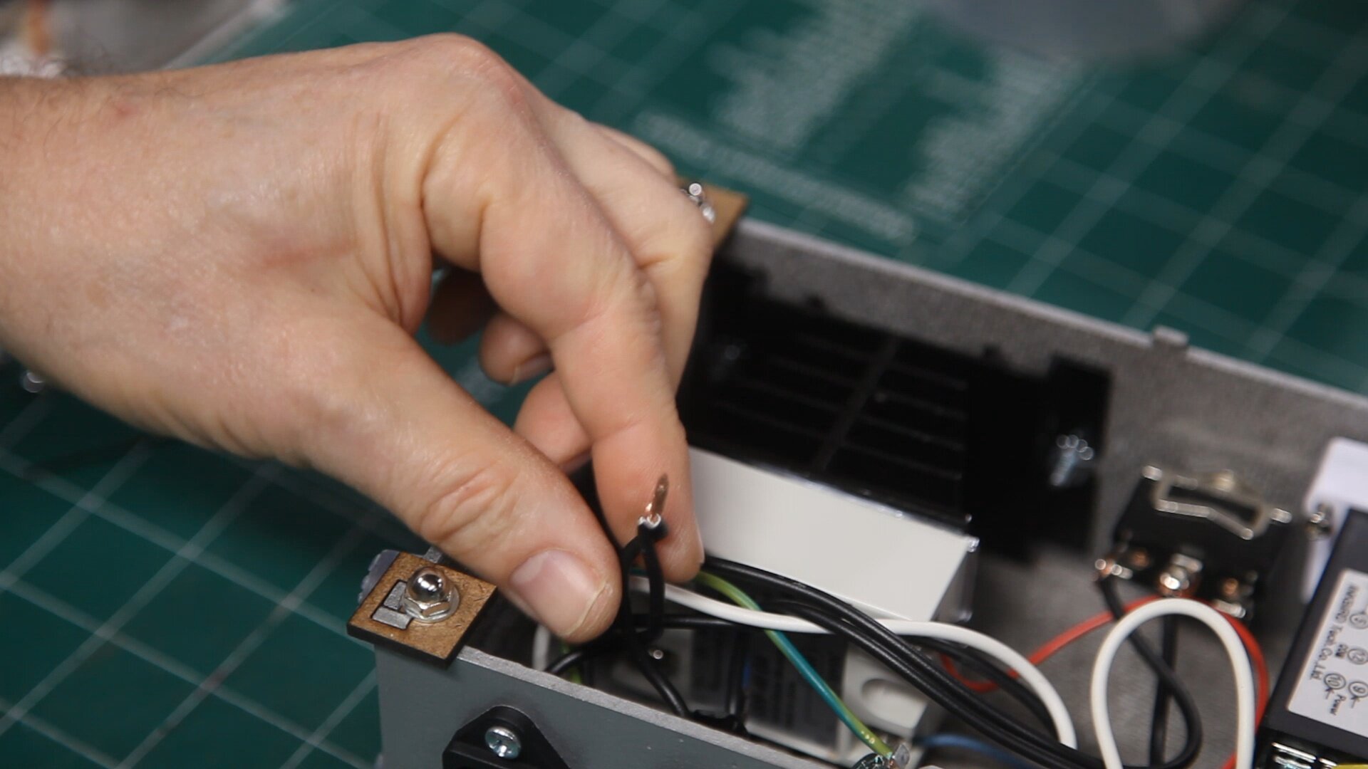
Step 11 - Connect Ground Wire
Strip about 3/4” of insulation from the green wire coming from the AC connector.
Connect this to the green terminal screw on the receptacle.
Step 12 - Connect Neutral to Receptacle
Strip about 3/4” of the insulation from the white wire connected to the AC input connector.
Connect this wire to the neutral terminal of the receptacle as shown here.
Step 13 - Connect Neutral to the PID
Strip 3/4” of the insulation from the white wire (power) coming from the PID terminal 9.
Connect this wire to the neutral terminal of the receptacle as shown here.
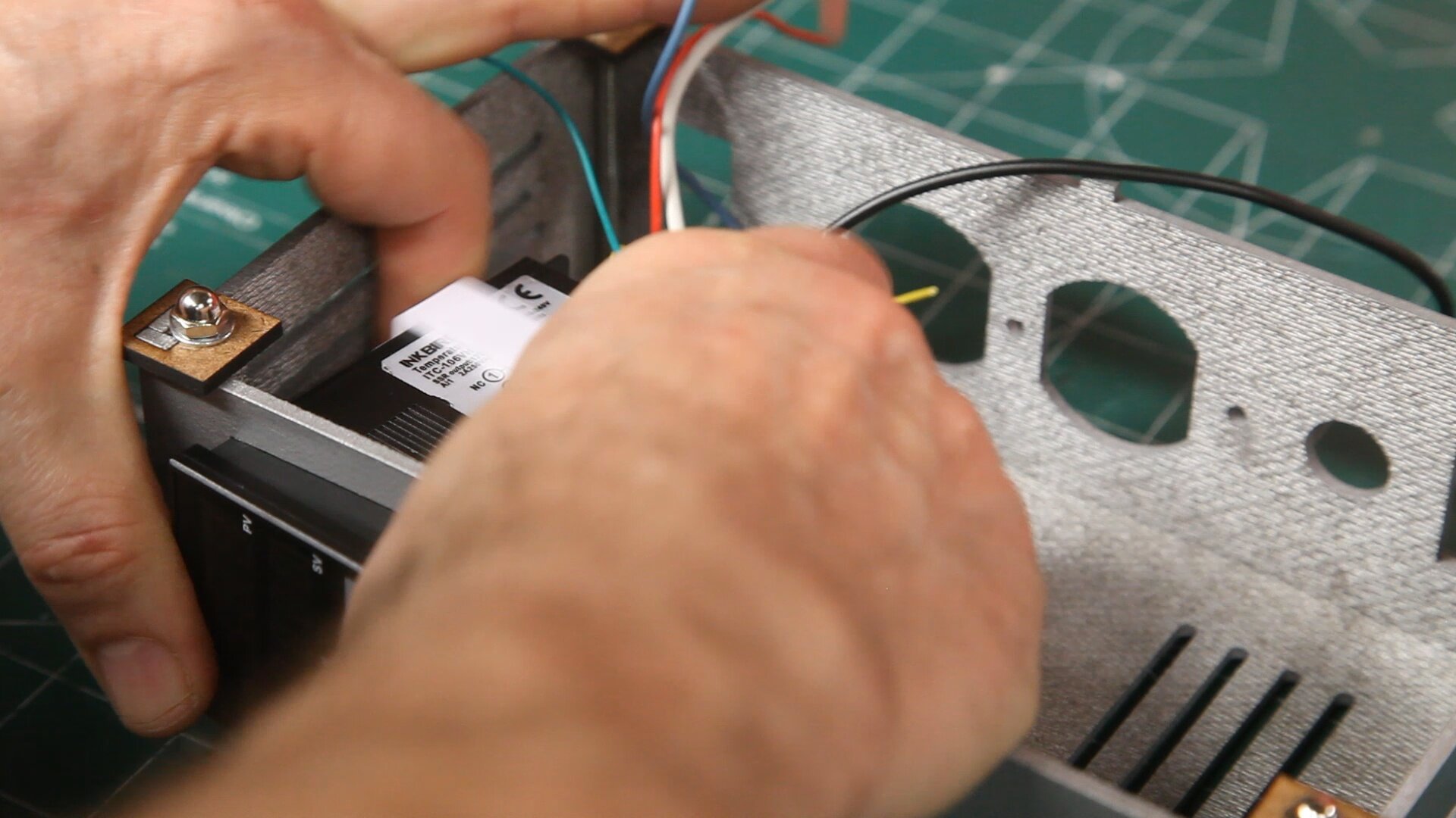
Step 14 - Connect the Thermocouple Jack
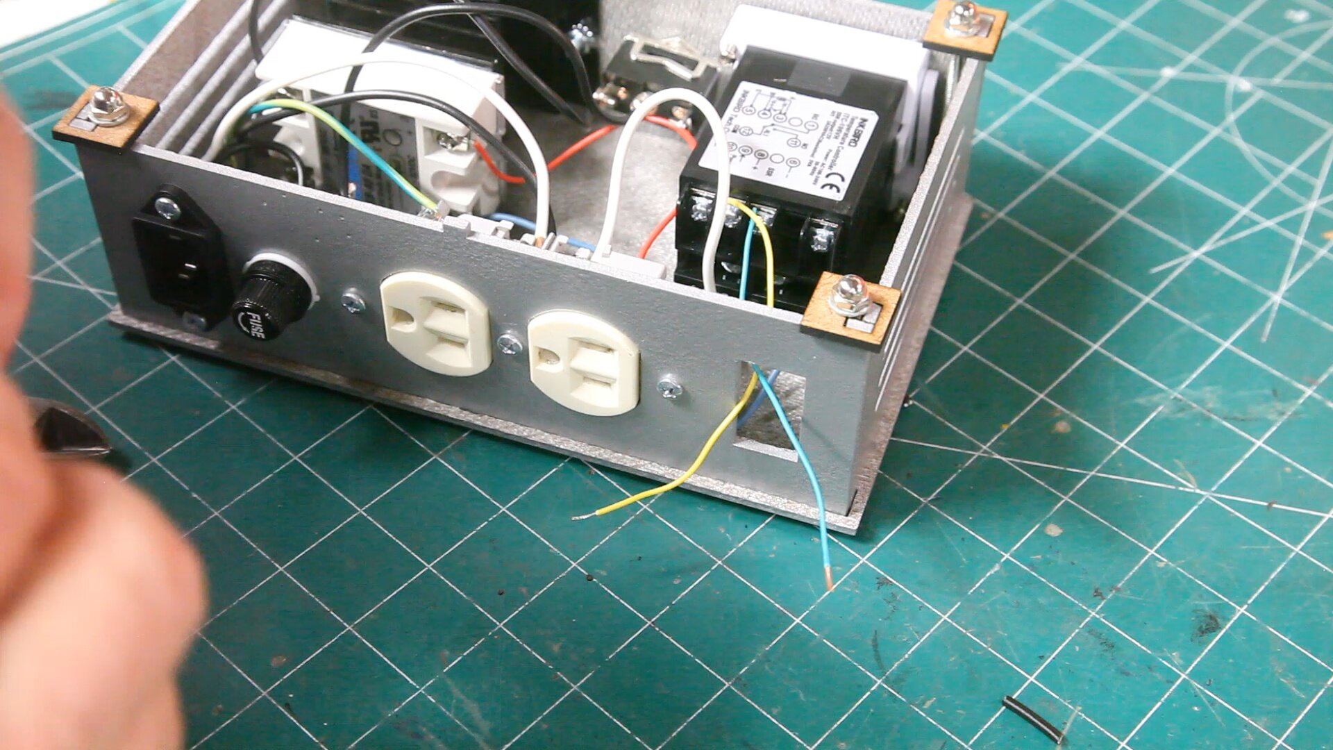
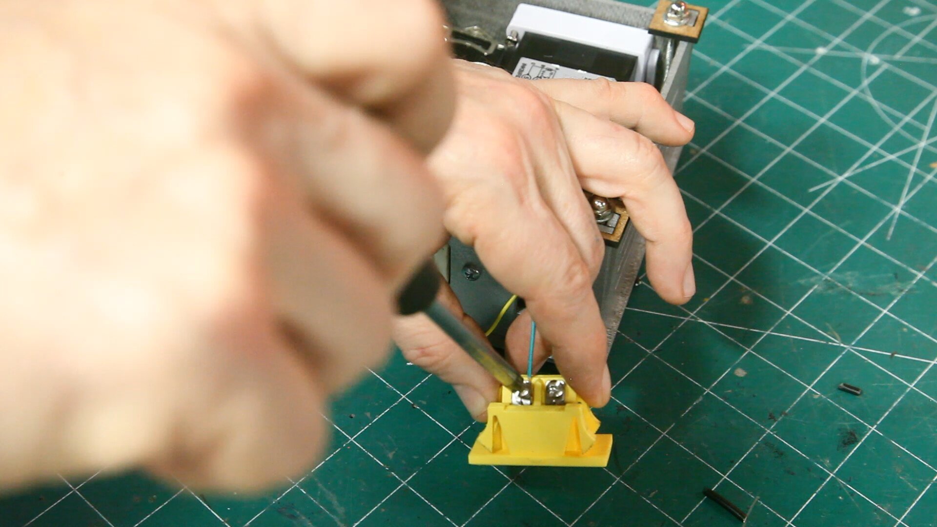


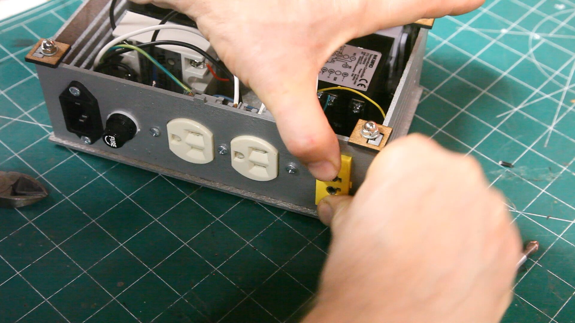
Take the green wire (TC-) connected to the PID terminal 3 and strip about 1/2” of the insulation. Connect this wire to the thermocouple jack marked -.
Take the Yellow wire (TC +) connected to the PID terminal 4 and strip about 1/2” of the insulation. Connect this wire to the thermocouple jack marked +.
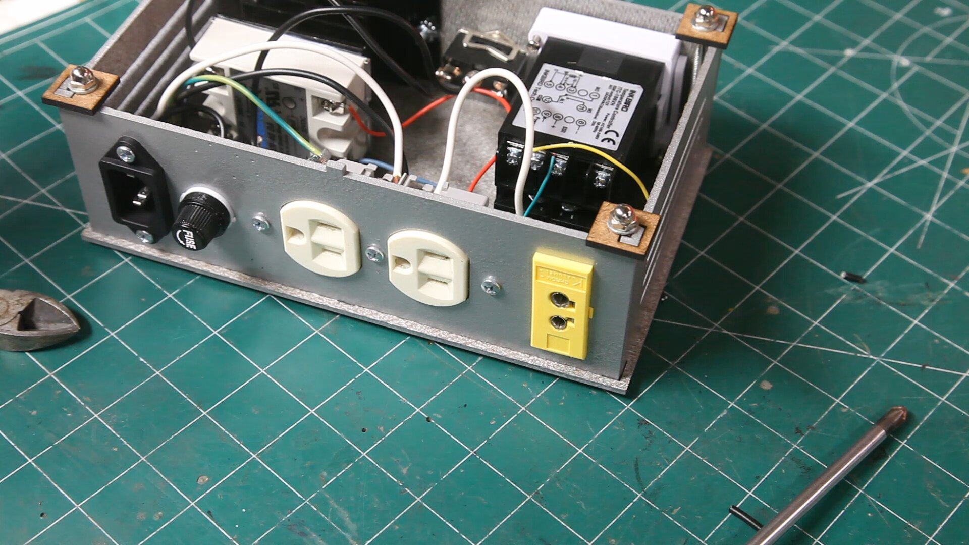
Push the jack into place.
Step 15 - Install Rubber Feet (Optional)


Insert a #6-32 x 1/4” machine screw into the recess on the rubber foot. Use a screw driver to push the head of the screw into the recess.


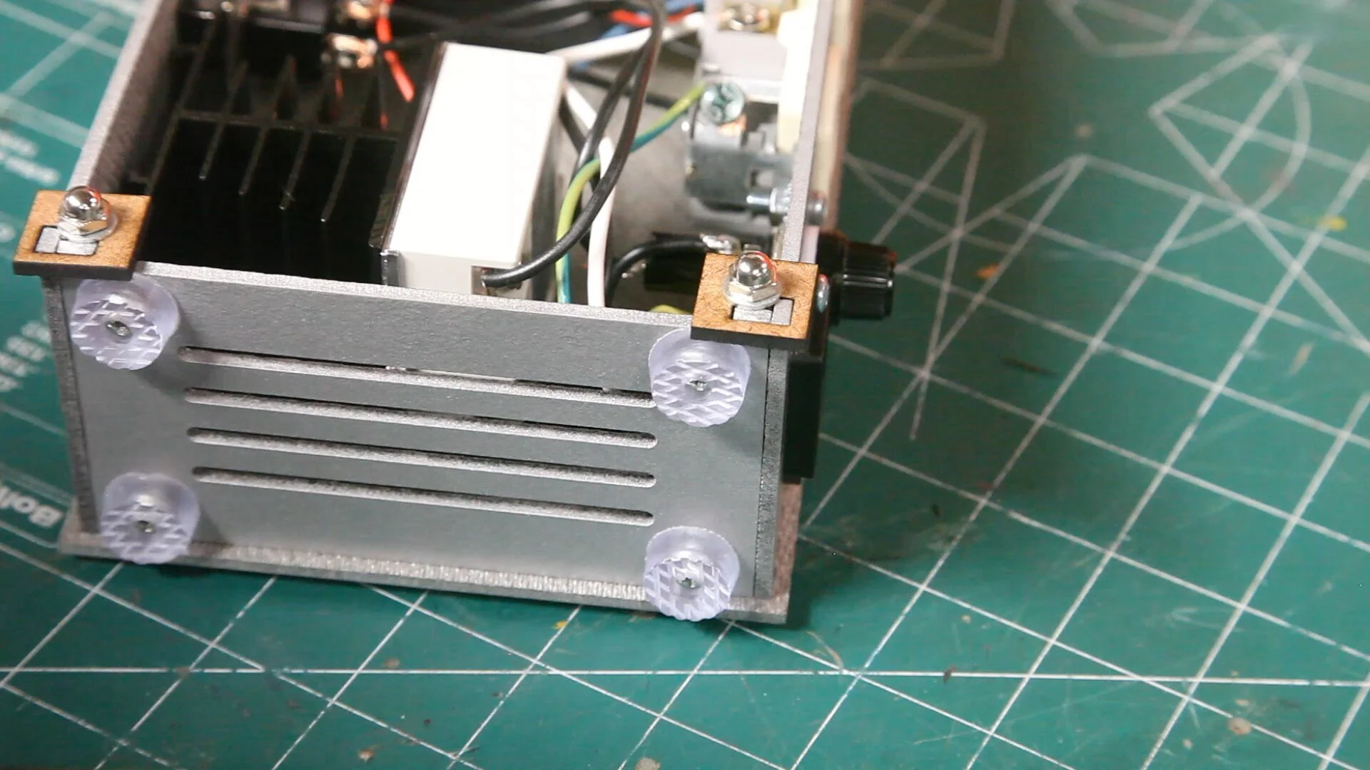

Install the feet into the holes on the side panel.
The side panel becomes the bottom panel in vertical orientation.
Conclusion
This concludes this portion of the universal PID build.
Resist the temptation to connecting power to the controller as I will show you how to do some simple tests before connecting AC power.
Help
If something is not clear to you, be sure to use the contact form below and I will help clarify the instructions.