

In The Beginning

About five years ago I designed and built an enclosure that would hold both my PC and my CNC electronics.
The one shown here was very compact and fit under my 18" x 14" KRMx02 build.

It worked so well that I designed a similar one for my 30" x 27" KRMx02 build.
Building the All-In-One Enclosure
Here is a video of me building one of these cases.
The Problem

While this design is compact and self contained, it is a nightmare to repair.
Here I had to remove much of the CNC electronics, just to get at the hard drive.
The Solution

I recently started playing with DIN rail systems and decided to break the KRMx02 CNC electronics down and mount them on one of my DIN rail proto boards.
I will also be doing a PC build on a DIN rail in the near future. While they consume much more space, they are easyer to trouble shoot and to upgrade.
The KRMx02 Basic CNC Electronics Build
I am not going to get into all the connections, as these are covered in the book. I will attempt to parallel the instructions in the book and try and keep the layout as close as possible.
The workbook layout and mounting of the CNC electronics was designed to make your first hookup as simple as possible. Even if you plan on mounting all your electronics in an enclosure, it is still recommended that you do your first electronics hookup as outlined in the workbook.
The goal here is to give you a DIN rail option for you KRMx02 electronics. Please note that doing a DIN rail layout such as this is not cheap, and can add over $100 or so to your build.
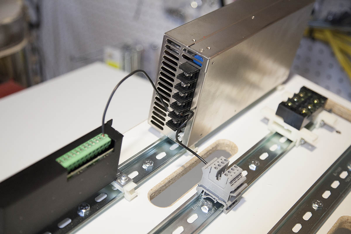
Mounting the G540
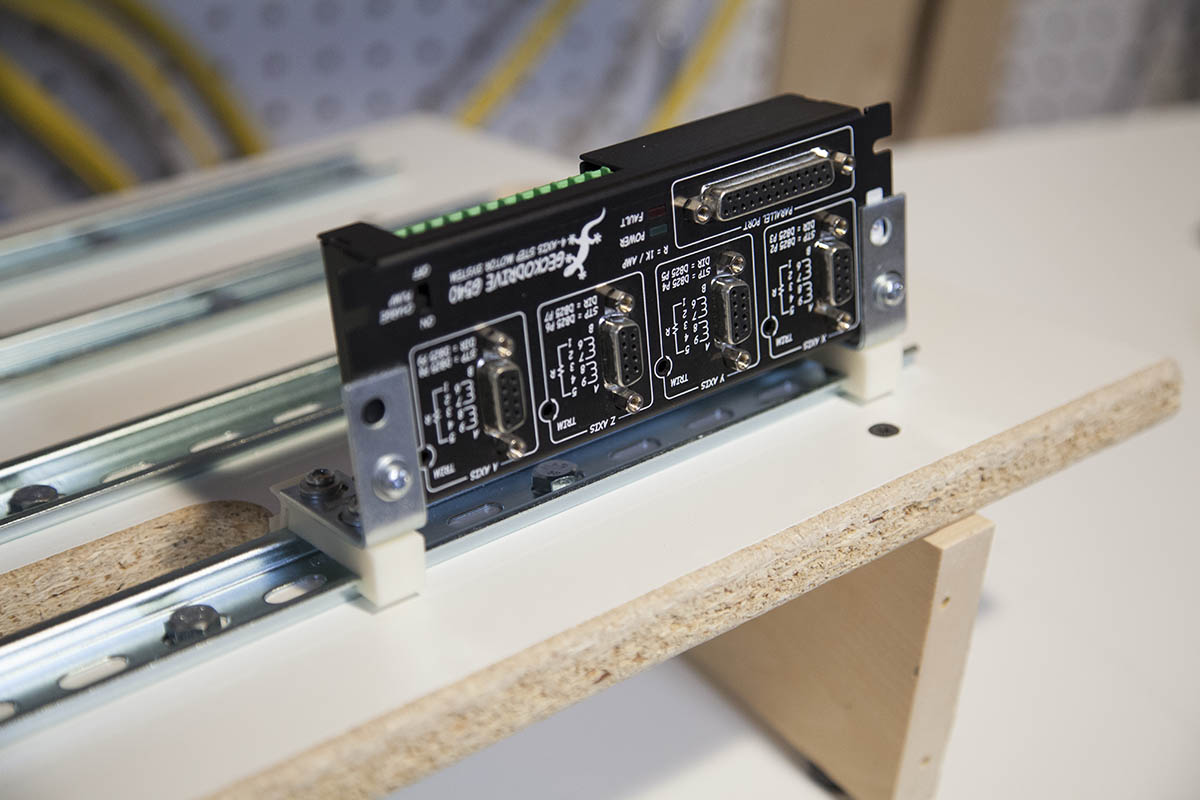
The G540 is attached to two DIN rail brackets with a couple steel corner braces.
They are held in-place with #6 machine screws.
The placement is in the upper left hand corner of my proto board.
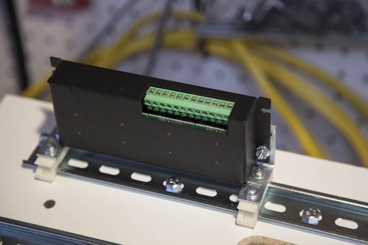
Note that the G540 is mounted upside down. This is so that you have access to the screw terminals.
Mounting the 48V Power Supply
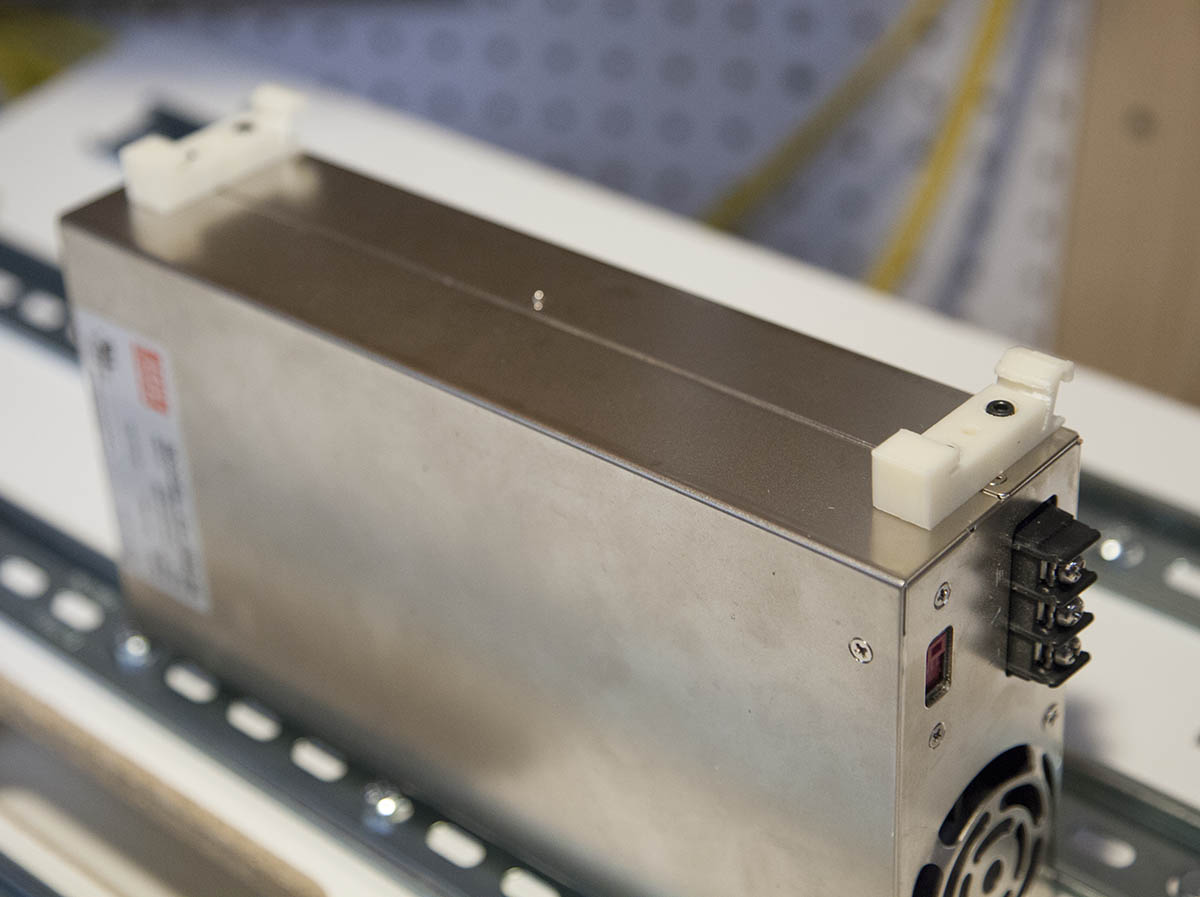
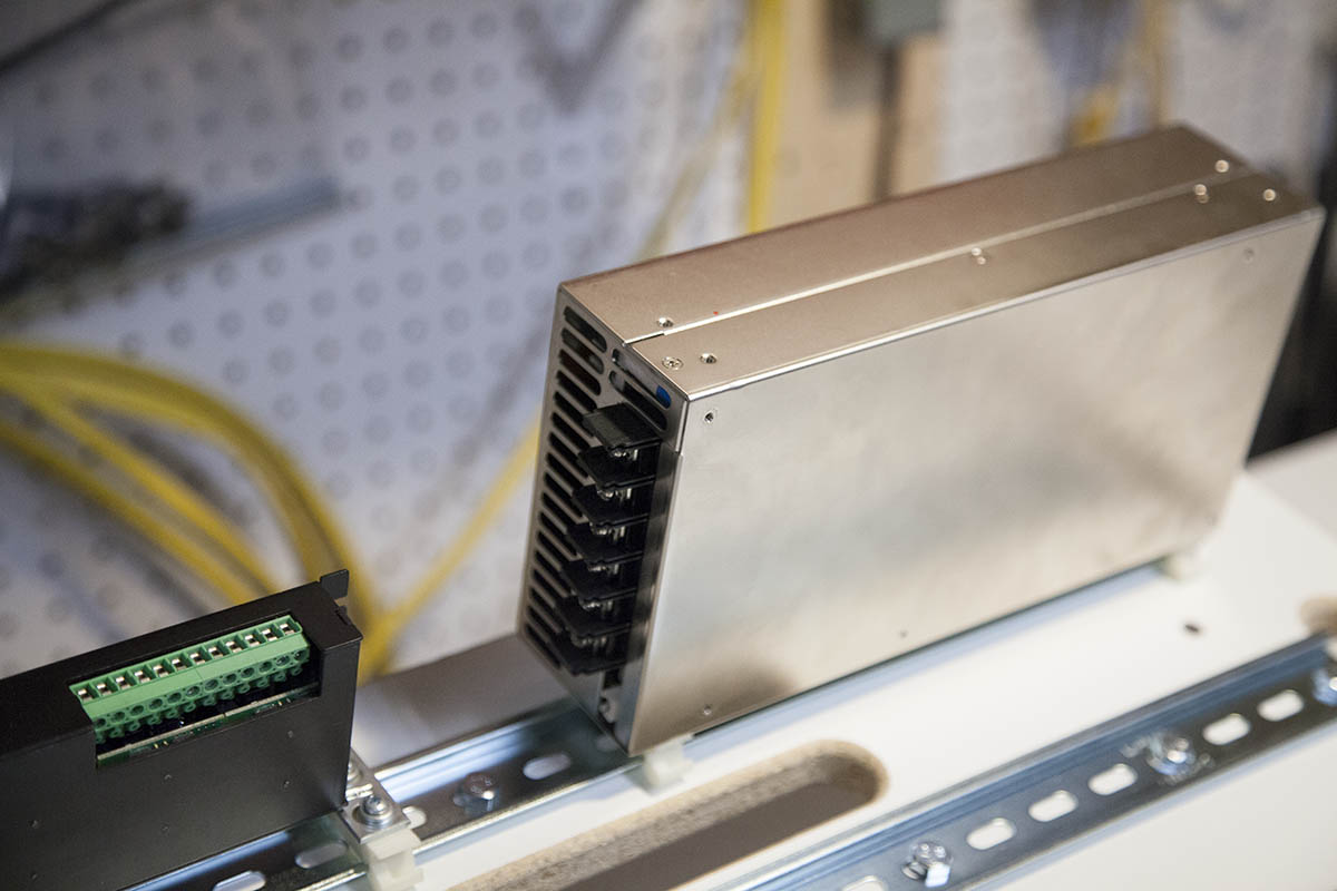
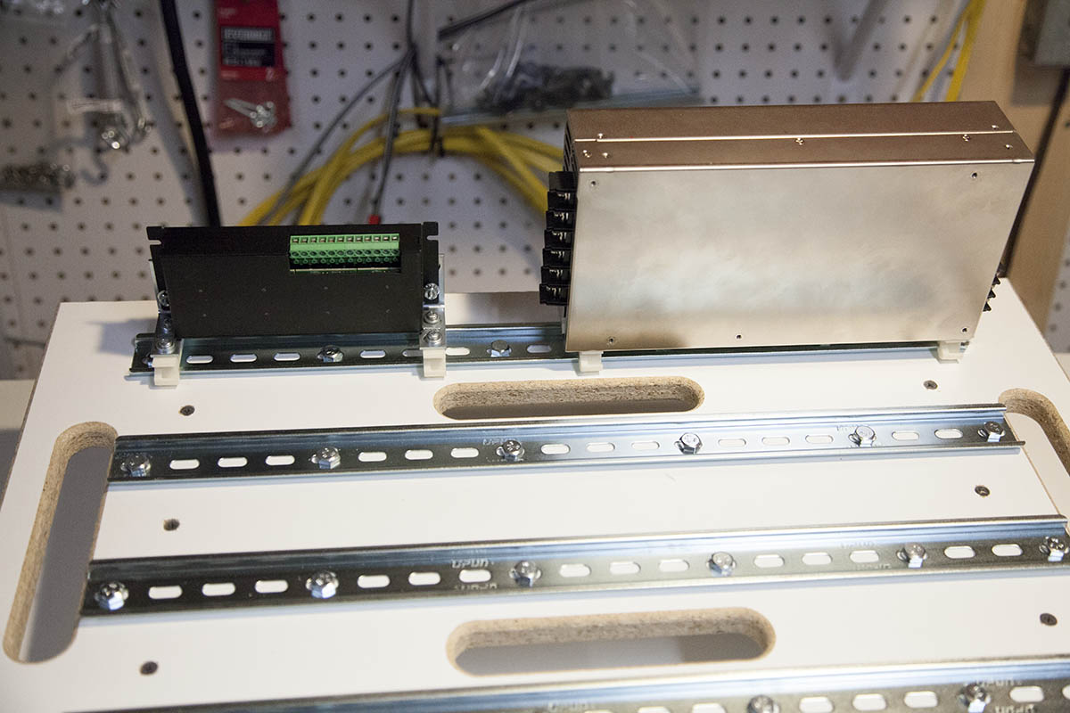
I mount some home made brackets to the power supply as shown here. Note that these are some early brackets and that my newer universal short brackets will work just fine here.
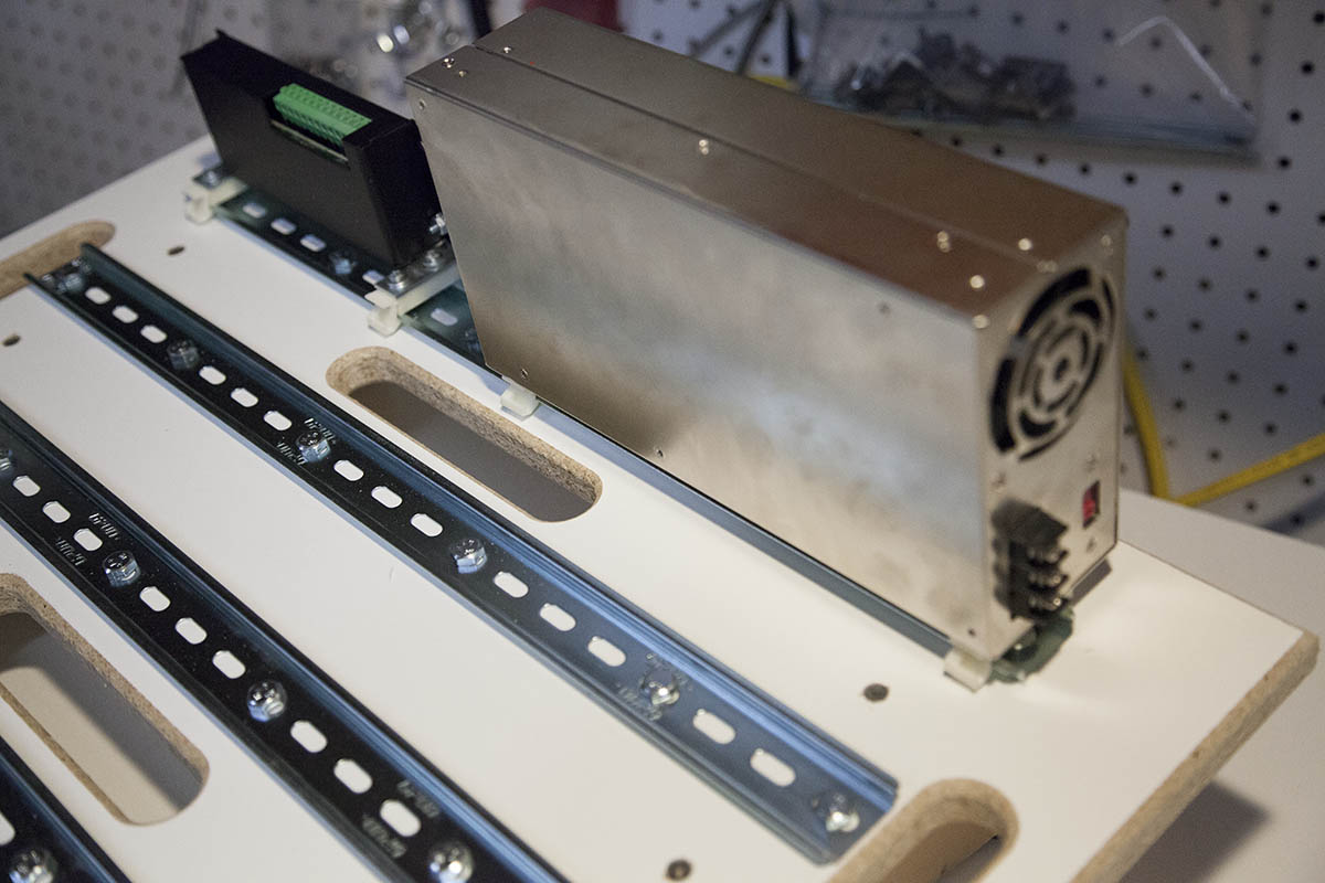
The power supply is mounted in the upper left corner of the proto board.
The AC connections are on the right hand side.
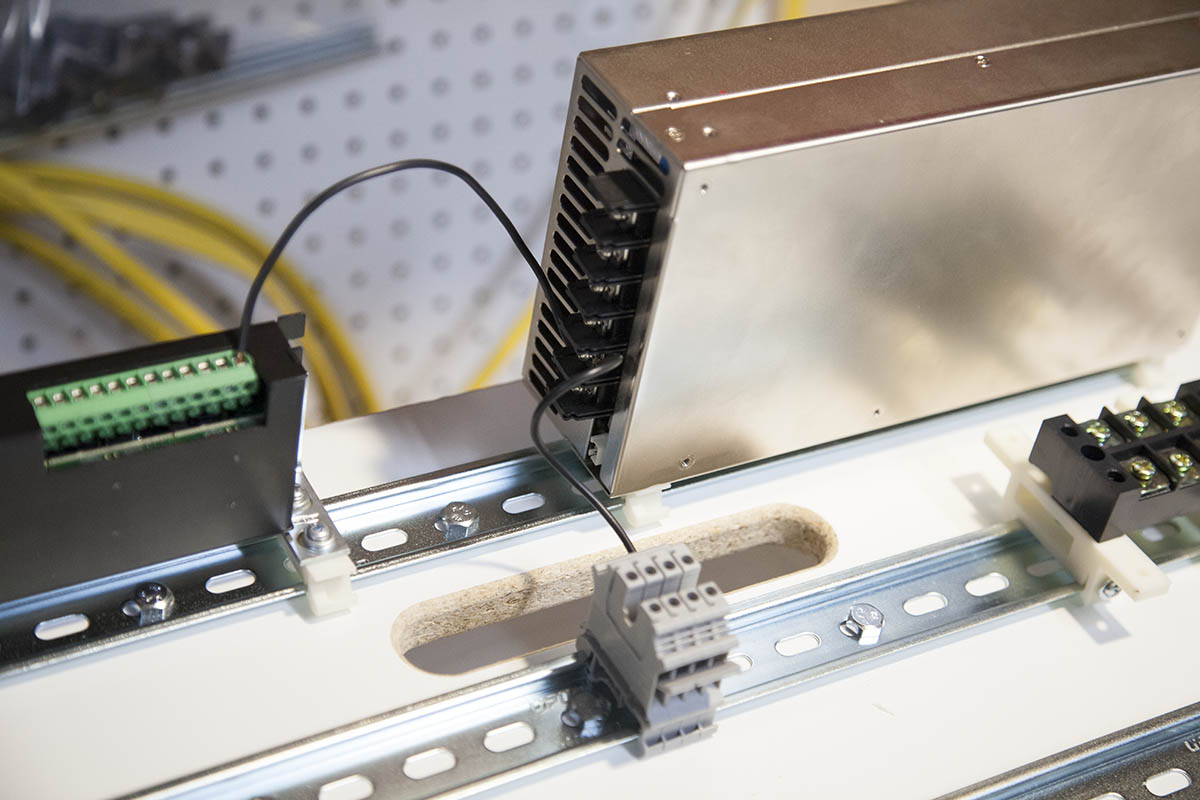
Mounting the AC Terminal Block

I mounted a three terminal heavy duty terminal block just behind the power supply as shown here.
You can get some of these terminal blocks here:
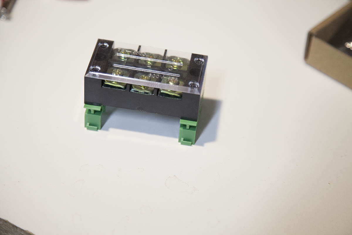
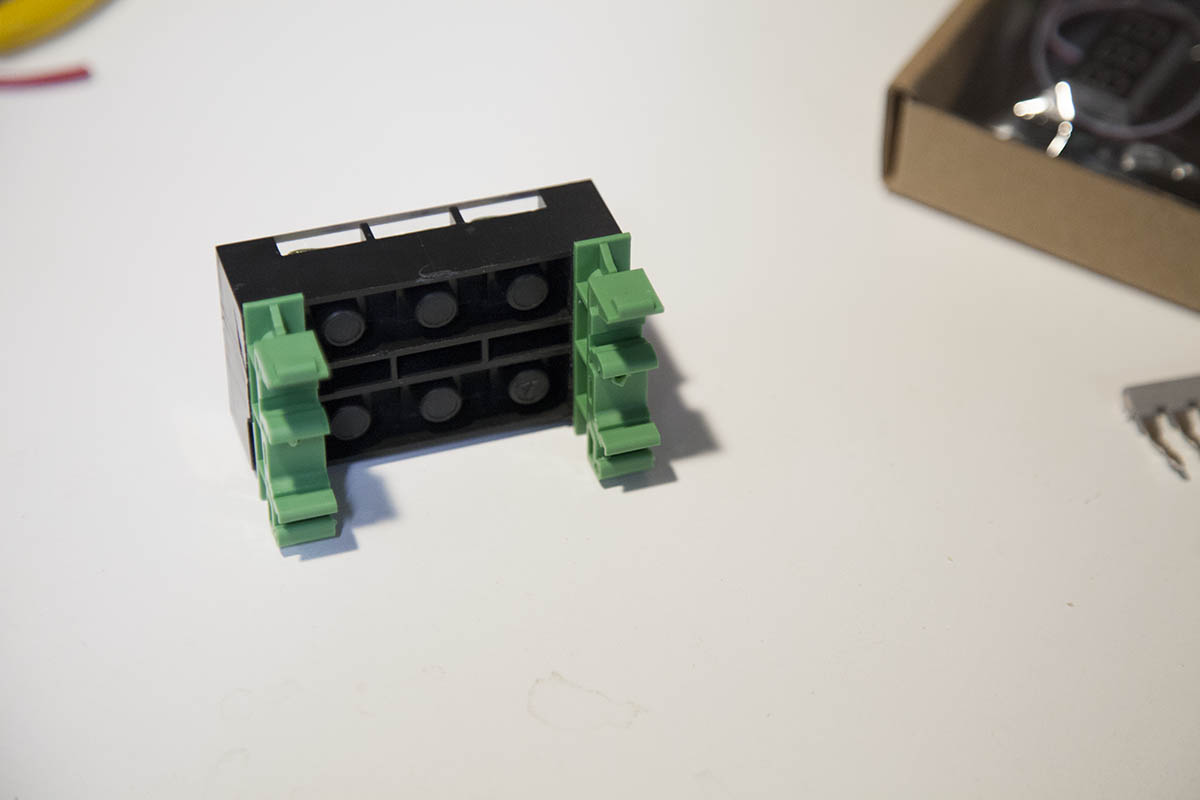
Above I use some 3D printed mounting brackets to mount the terminal block. Here I used a set of PCB mounting brackets I purchased.
You can get them here:
or
Mounting V- Terminal Blocks

I mount four grey DIN rail terminal blocks into the position shown here.
I used grey because that is what I had on hand. You can use any color you happen to have.
I will cover DIN rail terminal blocks in depth for this series in the next couple days.
Wiring V- Terminal Block
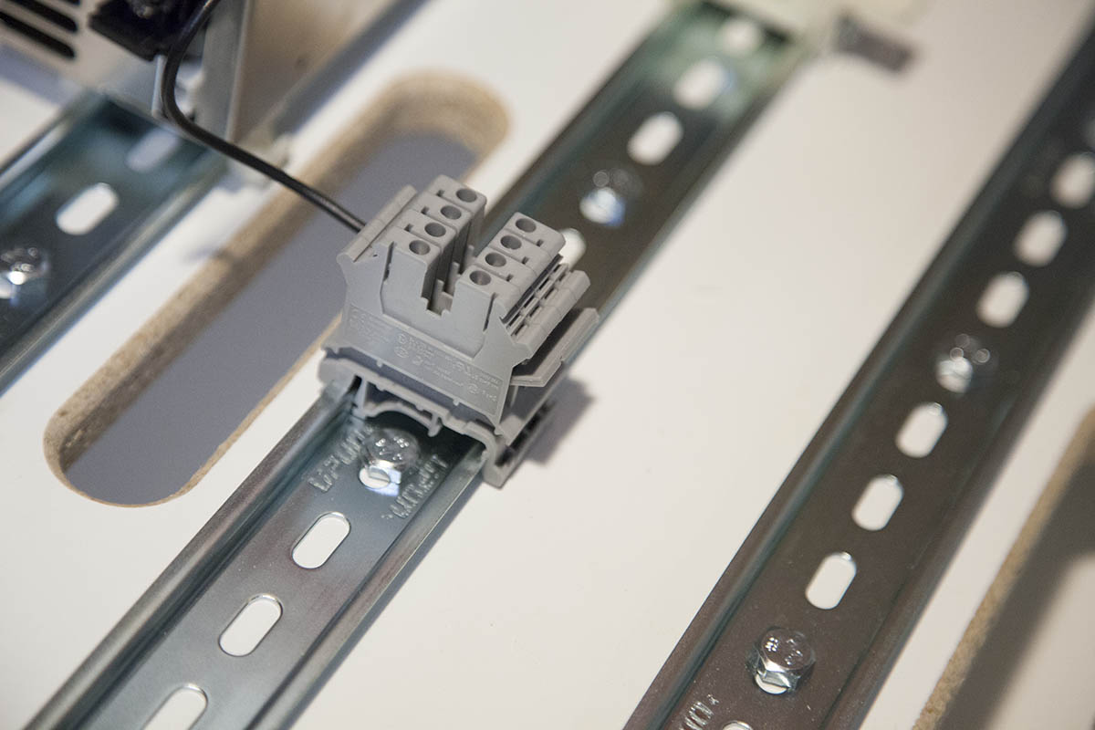
I added a four position shorting strip to the front of to terminals. I will cover shorting strips in the terminal block section.
On the back of the terminal block I connect a black wire between one of the blocks and V- on the power supply.
I then connect the negative power terminal on the G540 to a second V- on the power supply.
Mounting V+ Terminal Blocks
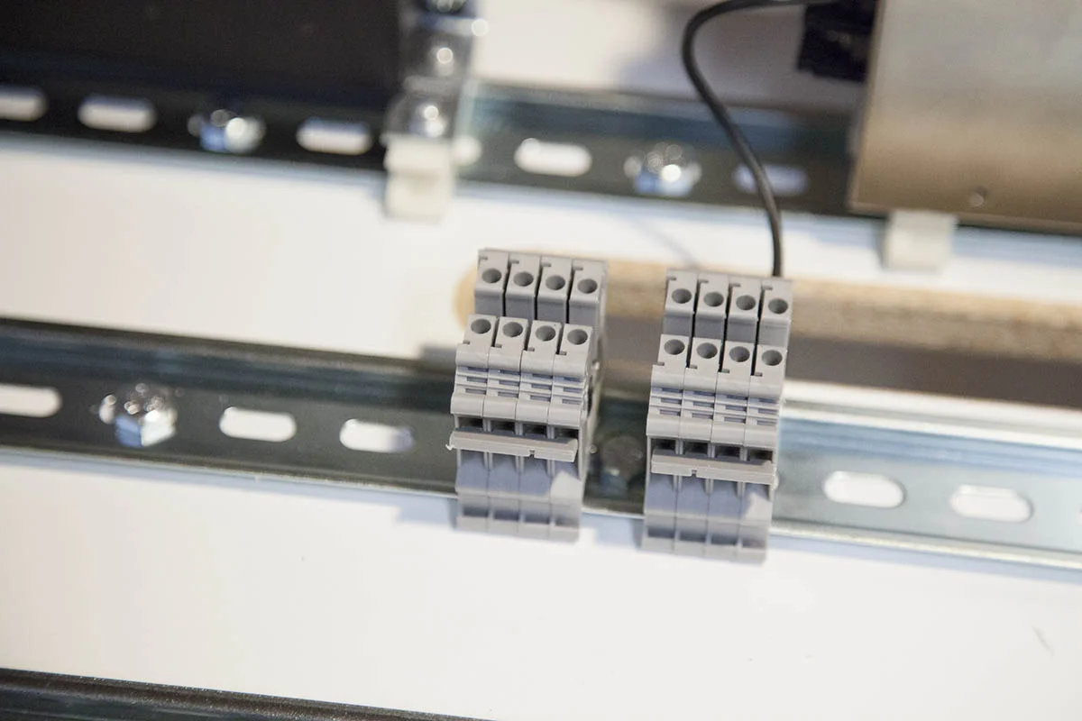
I mount four grey DIN rail terminal blocks next to the V- terminal blocks as shown here.
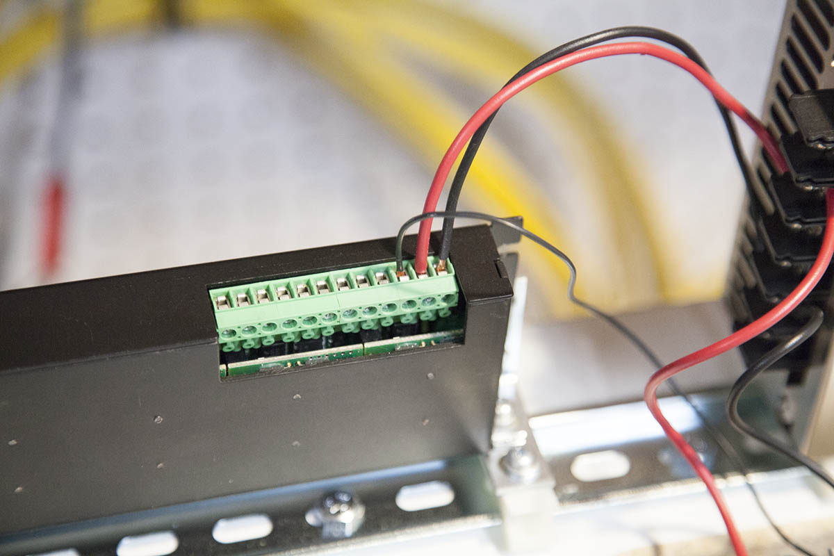
Wiring V+ Terminal Block

The V+ terminal blocks are wired exactly the same as the V-. The only difference is that they go to the V+ on the power supply and the positive power input on the G540.
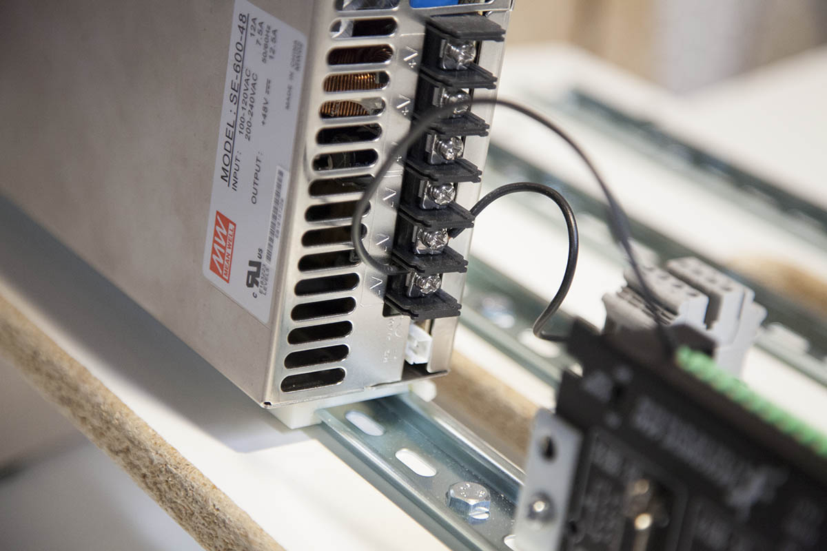
Wiring the Power Supply
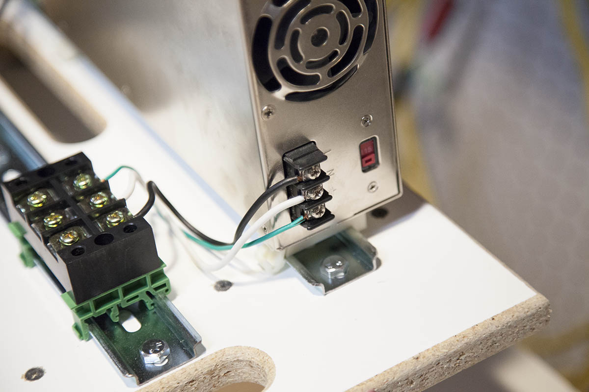
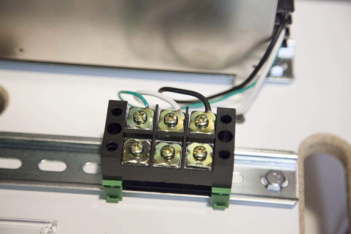
Here I have taken three wires, green, white, and black and wired them to the ground, Neutral, and Line terminals on the power supply.
Wiring EStop Bypass

As outlined in the KRMx02 workbook, you need to connect an Estop bypass between the G540 and the V- terminal block.
Estop Button Option

As an upgrade you can add a mushroom button instead of the bypass wire.
Note that an actual Estop button attached to the KRMx02 is covered in the KRMx02 Upgrade workbook.
Wiring AC Line Cord
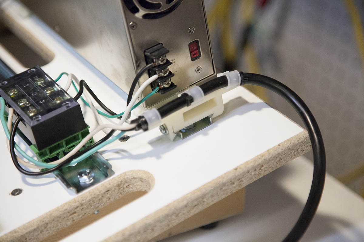

Here I have attached a three prong power cord to the three terminals as shown here.
Green should be connected to the same terminal that is connected to ground on the power supply. White should be connected to the same terminal that is connected to neutral on the power supply. Black should be connected to the same terminal that is connected to line on the power supply.
I also added a bracket with some cable clamps to help secure the power cord.
Power Switch Option

As an option you can connect a switch by cutting the black wire on the power cord and connecting each end to a switch.
This will allow you to power down the electronics, without having to unplug the cord every time.
Note that the terminal block comes with a cover. Use it!.
Fan Hookup
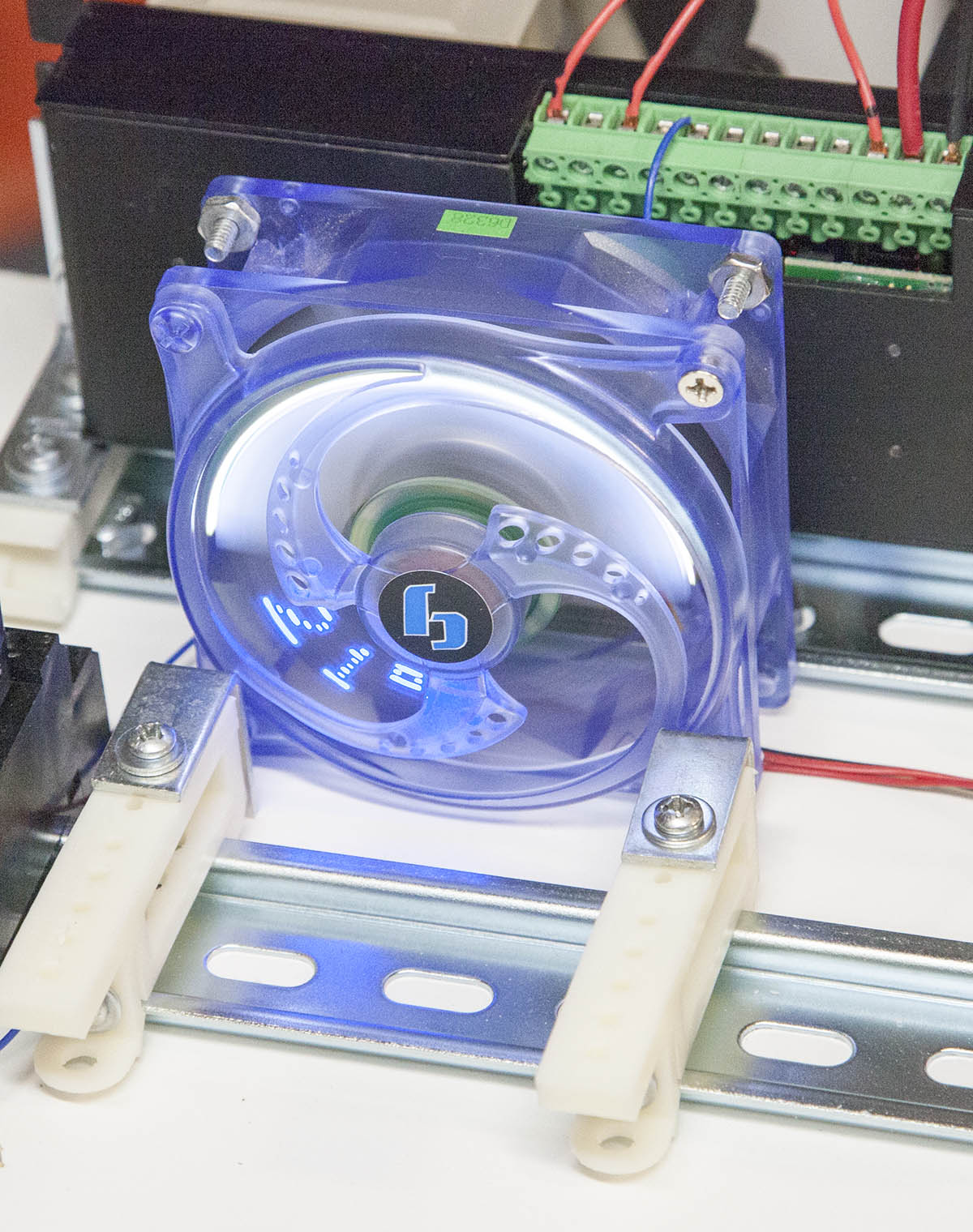
If your shop gets warm, you may want to add a fan to help keep you G540 cool.
Here I added a couple right angle brackets toa 12V PC fan. They are attached to some of my longer DIN rail brackets.
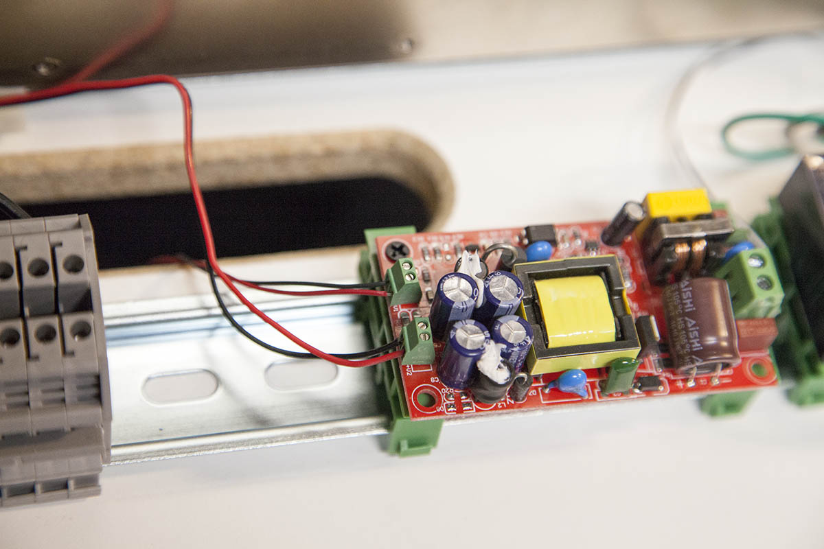
The down side to adding the fan is that you will need a 12V power source. In my case I used a small open frame, duel power supply.
This one supplies both 12V and 5V that I will need later when I attach a SuperPID speed controller.
You can get one here:
Conclusion

This is enough to get your KRMx02 up and running. The workbook will take you thorugh the Mach3 installation, setup, and testing of the KRMx02.