

The information presented here is meant to augment the SuperPID upgrade I presented here:
Its primary purpose is to show the hookup using a DIN Rail system. In addition, I am going to assume thatyou made the modifications to your router to effect full closed loop control, as covered in the above upgrade instructions.
SuperPID 2 Basic Hookup
In this section you are going to connect your SuperPID in an open loop. This means that the router will not provide feedback to the SuperPID.
This is great way to get started and make sure the basic wiring is correct.
!! Please note that in addition to the wiring shown here, you will also need to connect a wire between the OP terminal and Ground. This tells the SuperPID that it is in open loop mode. This connection was not covered in the hookup instructions.
Mounting the SuperPID 2
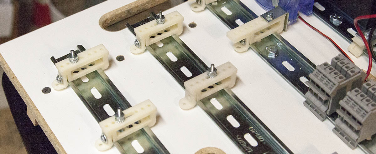
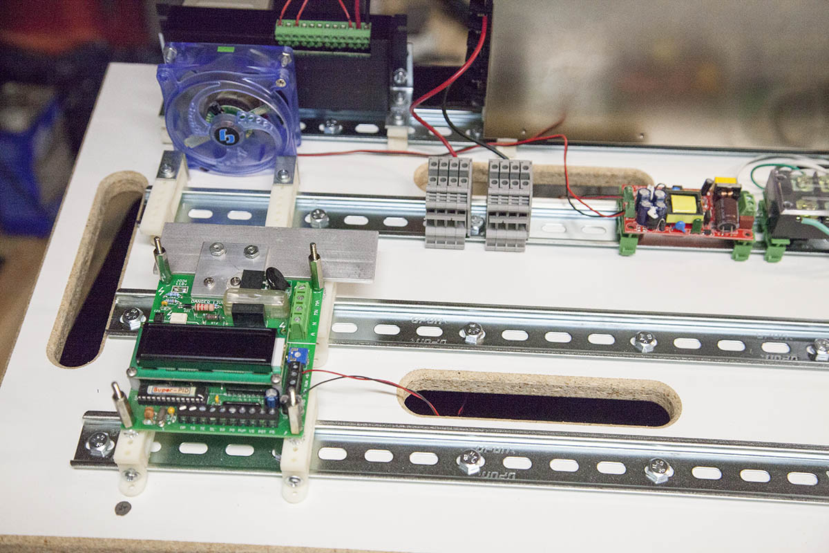
To mount the SuperPID I am using 4 of my "KR Universal Short DIN Rail V8".
Notice the two nuts on each post. This is to raise the board up for clearance.
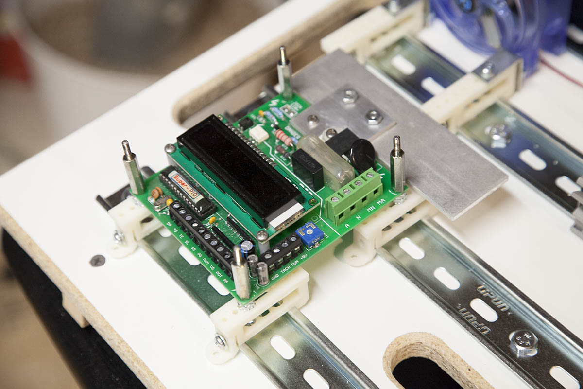
The board is installed on the posts and secured with standoffs. These standoffs will allow me to mount some sort of cover later.
Powering the SuperPID 2
The SuperPID needs a 5v power source. You can use a standalone power supply or some sort of buck converter.
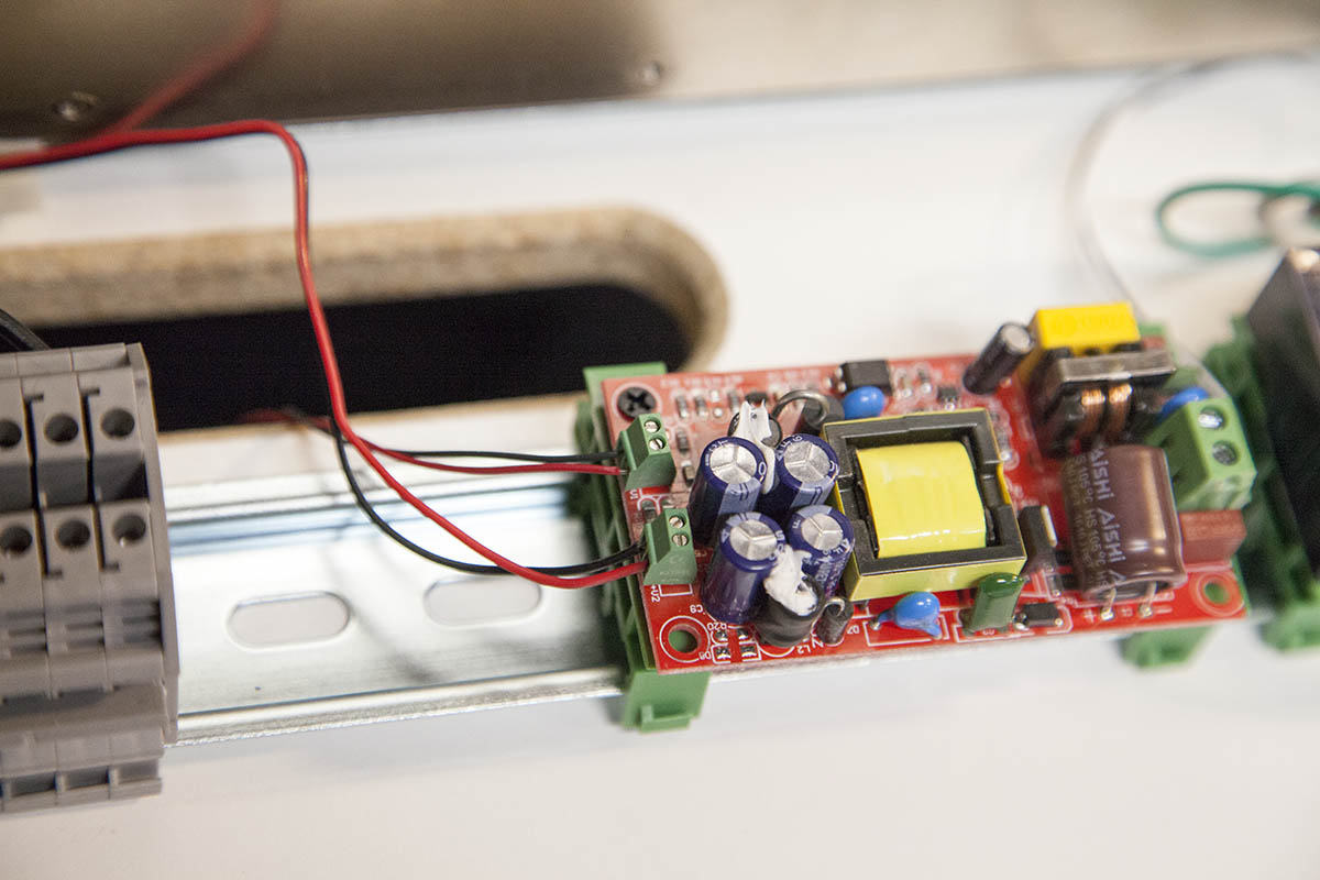
In my case I ended up using a small dual power supply that I had installed when I started my KRMx02 experiments.
This open frame power supply has both 12v and 5v outputs.
Notice how I used the slots in the proto board to rout the wires under the board.
Attaching Potentiometer
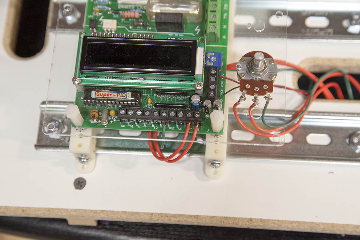
You need a potentiometer for manual control of the router speed. This done by connecting the first lead on the potentiometer P5 on the SuperPID.
Attach the center lead on the potentiometer to the POT terminal on the SuperPID.
Attach the last lead on the potentiometer to the PG terminal on the SuperPID.
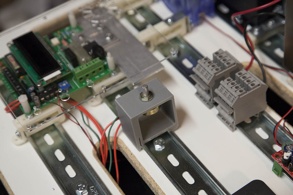
You can mount your potentiometer if you like, but we will be removing it in the next section.
Attach Mach3 Control Wire
In order for Mach 3 to turn the router on and off, you need to attach a wire between the RUN terminal on the SuperPID to terminal 5 on the G540.
Attach OP Jumper
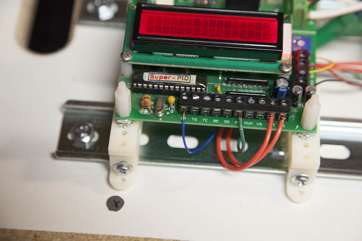
Add the open loop jumper by running a wire between the OP terminal on the SuperPID to Ground.
Power Test
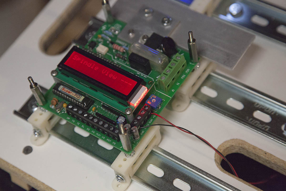
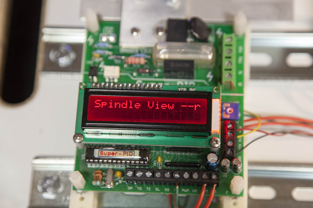
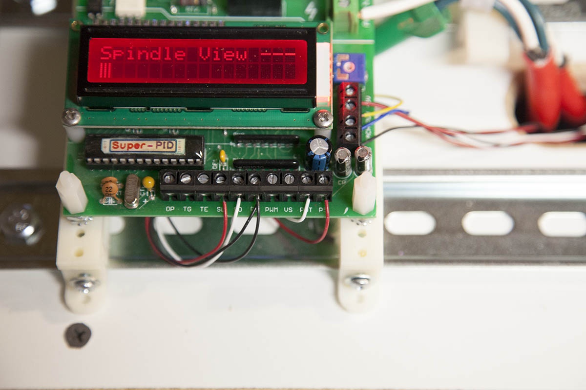
When you apply 5V power to the SuperPID, it will boot, displaying its current version then will default to the spindle view.
If you turn the router on using the Mach3 signal a small r will appear as shown here.
Obviously since we have not connected the AC source or the router, the router is not going to start.
Please refer to the SuperPID Upgrade pages I created for Mach3 confiuration.
Connecting AC and Router
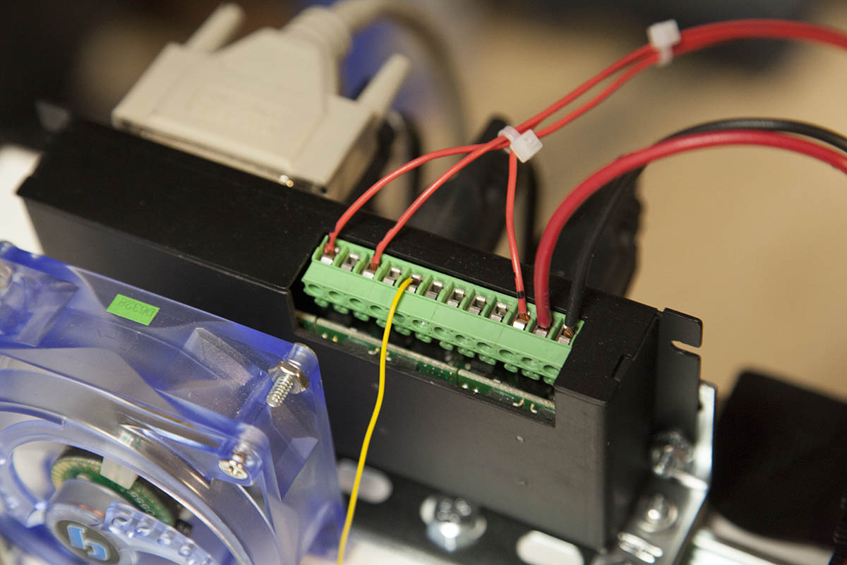
It's time to connect AC to your SuperPID. In the process we will also connect the router. Both are done through the same terminal block.
What I do is purchase an extension cord and cut it in half. I connect the plug(M) end (Black=A, White=N) to the A and N terminals. I connect the socket(F) end (Black=MA, White=MN) to the MA and MN terminals.
The two green wires are twisted together and secured with a green cap screw.
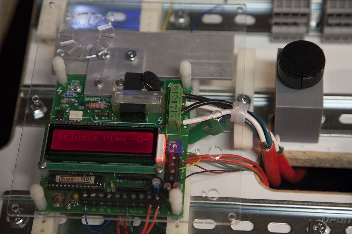
When you plug into the AC source and power up the SuperPID with the 5v power supply, the Super PID will alert you during the power up sequence that it found the AC Mains.
The O in the spindle view indicates that the router is in open loop mode. Once Mach3 starts the router, it will also display a capital R to indicate it is in run mode. Use the potentiometer to raise or lower the router RPMS. Note that because the speed sensor has not been connected, the SuperPID will not display RPMs.
Connect the Speed Sensor
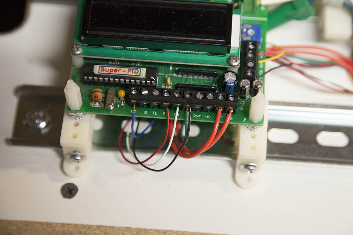
By connecting the router RPM sensor you can start monitoring your routers actual speed.
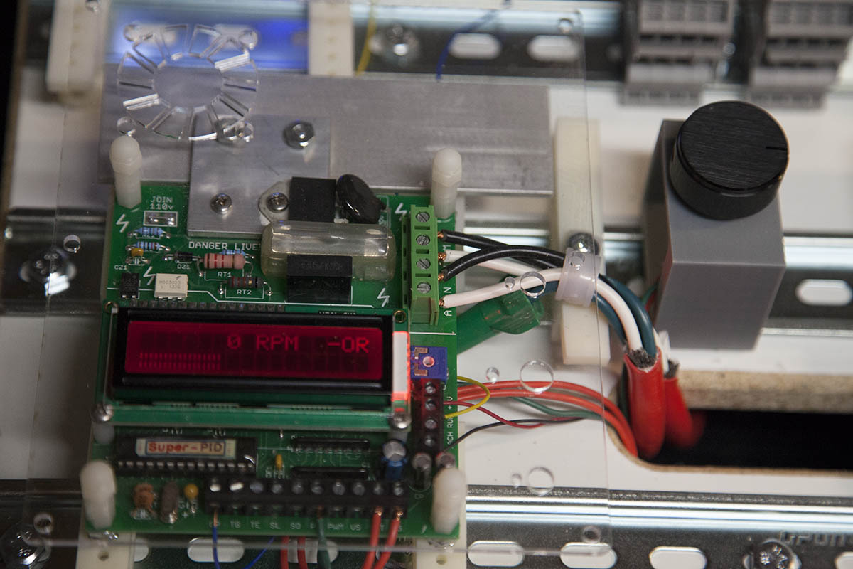
Connect the red sensor wire to the SL terminal. Connect the black sensor wire to the PG terminal. Connect the white sensor wire to the SO terminal.
Now when you power up the SuperPID and start the router, you will be displayed with the actual RPMS the motor is turning.
SuperPID 2 Full Hookup
Once complete, Mach3 will have on/off and speed control of your router.
Full (advanced) hookup requires the removal of the OP jumper and the potentiometer.
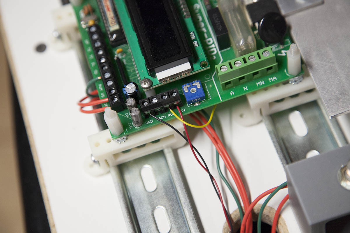
Connecting the G540
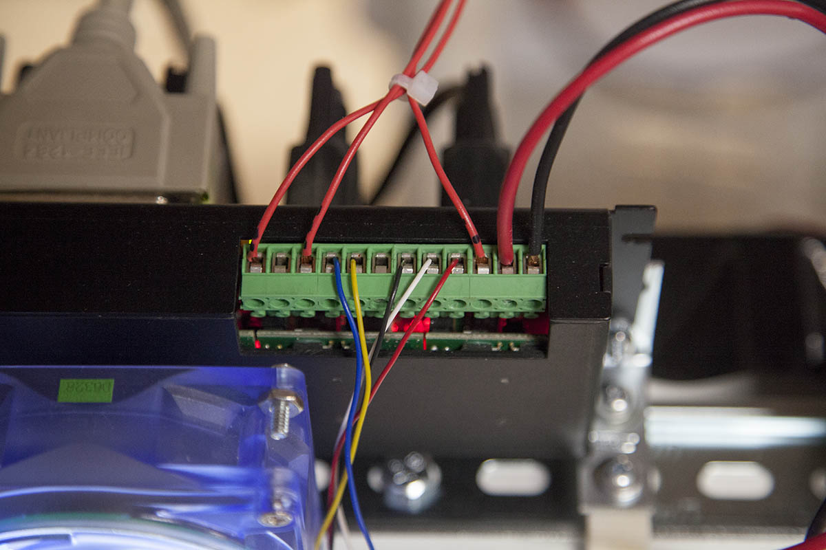
The only real difference to full control and manual control is the removal of the potentiometer and the connection of the SuperPID to the G540.
Connect:
G540 Port 7 to SuperPID Terminal PG
G540 Port 8 to SuperPID Terminal POT
G540 Port 9 to SuperPID Terminal P5
G540 Port 4 to SuperPID Terminal TACH
At this point you can configure Mach3 with the settings shown in the advance wiring project.
Conclusion and Testing
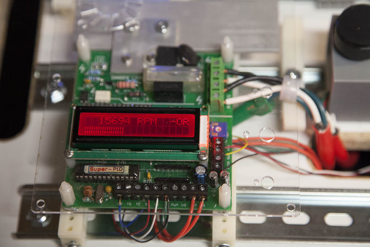
Power up your CNC and ensure that Mach3 is in active mode (Reset=Green). When you hit the Spindle CW button you should see the SuperPID go into run mode. The motor RPMs will be displayed both on the SuperPID and in the RPM field in Mach3.
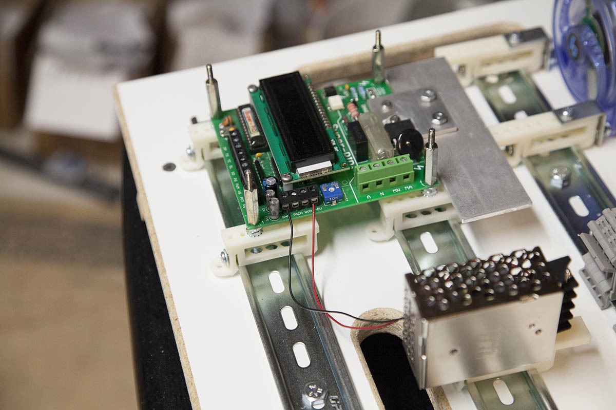
SuperPID in Action
Here is the SuperPID 2 controling the router as I cut this DIN rail proto board.