

CNC Part Creation Workflow
New to CNC these examples may help
In this project, I am going to take you step-by-step through the processes I use creating a part on my CNC. I will start with a idea take it from the drawing stage all the way thorough to the completed part. Even if you don't need this part, I recommend you follow along and actually create the part with me as I take you through the process.
If you just want to make the part for your KRMx02 CNC you can download the Gcode here.
Keep in mind the display shown below are based on the KRMx01 and KRMx02 screen sets. They may look slightly different than the Mach 3 screen sets you may be using. Regardless of the screen set, the operations are the same.
In this workflow I am using Vectric's software Cut2D. Cut2D has a big brother called VCarvePro. Its operation as far as this workflow is concerned, is the same. If you purchase Cut2D, you can later do an upgrade to VCarvePro.
Solve the Problem
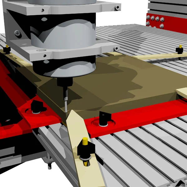
First I try and visualize the part I want to make. In this case I am trying to solve a problem. When I raise my Z axis too far the bearings disengage the rails. Not a disaster, but puts undo wear on the upper bearings. The answer is to add a stop block to the bottom of the Z-beam as shown below.

As you can see we have two issues that need to be over come. The first, we need two holes in our stop block that mate with the two threaded holes in the bottom of the beam. Second, we need a small pocket in the block so that we can clear the router mount screws.
The illustration below shows the finished part we need to create.

Software Tools
In order to bring the idea for this part into reality I will use three pieces of software.
First, I will use Corel Draw to design the part. This is the CAD aspect of the workflow. Once I have a drawing file of the part, I will export it into Cut2D.
Cut2D is used to create the tool paths for the CNC controller software. With Cut-2D I will choose the router bit and paths I want to take on each object in the drawing. Once this process is complete Cut2D will export a Gcode file to Mach 3. This is the CAM aspect of my workflow.
Mach 3 uses the Gcode file to tell the CNC machine where to move each of its axis. This is the control aspect of my work flow. This where the part gets made.
Before moving on let me say there are many pieces of software that can be used for the CAD, CAM and control aspects of a work flow. Some software will even combine them. The prices for this software can range from zero to thousands. With free software you generally get what you pay for. What I have chosen is on the low end of the scale but, I have found them to be very productive.
Step 1 - Design the Part
I start with a blank page in Corel and begin designing my part. In most cases its simple geometric shape like rectangles that make up the parts design. In the case of this part I do the following.
- I create a rectangle that represents the overall size of my stop block. In this case its 2" x 4.5".
- At 1.5" from the edge and .75" from the bottom I add two 3/8" circles.
- I then add two .75" x .75" rectangles to each of the corners.

Step 2 - Export the Part
The final part should look like one shown below. It consists of 5 shapes.

Select all 5 shapes and select export option in the File menu. Give the export a name and select the EPS type as shown below.

Step 3 - Import into Cut2D
Once I have my part exported, I load up Cut2D and load the EPS file.
When you start a new Cut2D project you get the Material Setup pane shown below. This allows you to setup the material you will be cutting your part out of. The Width and Height fields will contain the extents of the part, in our case 4.5" x 2"

The first thing you need to change is the width and height of your stock. This is the material you will be cutting your part from. I want a lot of room around the edge so I will choose a piece of stock 6" by 4", as shown in the Width and Height fields.
Next I set the thickness of the stock. In this case it's 3/4" thick or .75".
I un-check "Use origin offset" and check "Center vectors in material". This will center you part in the stock.
Also important is to make sure the XY Origin Position is referenced in the lower left hand as shown below.
I then click OK.

Step 4 - Create Holes Toolpath
The main reason for using Cut2D is to create toolpaths for the CNC. To do this I first select the shapes I want to create a toolpath for. In this case I am going to start with the two holes. I select both holes, then hit the "Create Profile Toolpath" icon located on the right panel, as shown below.
I am then presented with the 2D Profile Toolpath pane shown below. The first thing I change is the depth I want the router bit to cut to. Keep in mind this is not what is cut in a single pass. The toolpath will make precise cuts, progressing deeper with each pass until this depth is reached. In this cas I want to go .02" beyond the stock so I choose .77"
The next thing I do is to select the tool I want to use. In this case I am going to use a .25" End Mill. I could devote a whole project in selecting, editing and using tools. For this project just choose the default .25" End Mill"
I want to cut the center out of the circles so I click on the Inside option for Machine Vectors.
The last thing I do here is name the toolpath. This is helpful when you have many and need to go back and edit one or more.
I then create the toolpath by hitting the "Calculate" button.

Once the holes are calculated I am presented with a preview pane. Here I can click the Preview Toolpath button and see the effect it has on my stock.

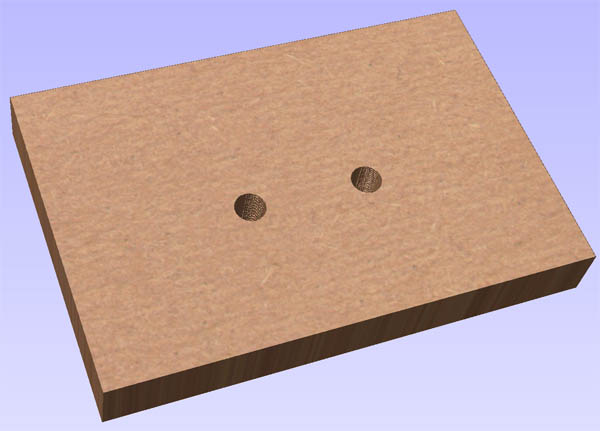
Also notice that we now have a toolpath listed in the top of the right pane called "Holes". This represents the actual toolpath I just created.
Once I am done with the preview pane I close it.
Step 5 - Create the Pocket Toolpath
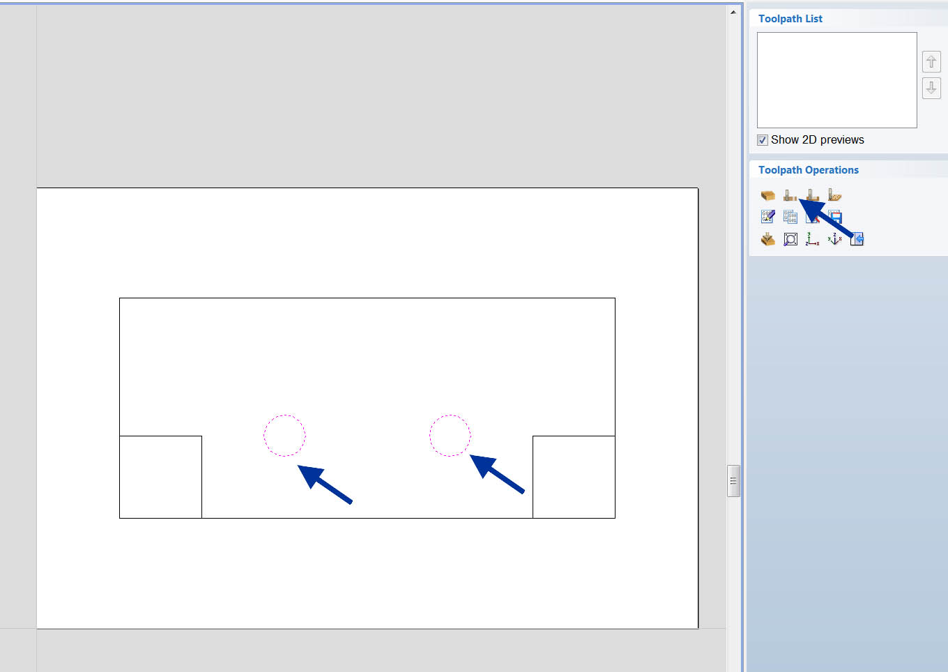
In order to create another toolpath I need to get back to the drawing. To do this I hit the Zstop.eps tab in the upper right of the display pane as shown below.

To create the two small pockets in the corner I select the two 3/4" rectangles and hit the "Create Pocket Toolpath" icon, as shown below.

I am then presented with the Pocket Toolpath pane shown below. Again the first thing I change is the depth of the pocket. Again the router will not do this in a single pass. I want my pocket to be 3/8" deep or .375.
The next thing I do is to select the tool I want to use. Again I am going to use a .25" End Mill.
There are a couple options in the way the pocket is created. For now I am going to choose offset.
I change the name of this toolpath to pockets and create the toolpath by hitting the "Calculate" button.

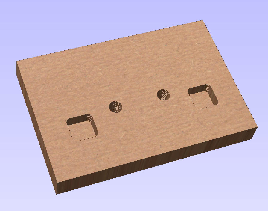
Again I am presented with the preview pane. I hit preview toolpath and the 3D display pain is updated showing the results of my latest tool path.
As before, I close out the preview pane and select my drawing tab.
Step 6 - Create Final Toolpath
The last toolpath I need to create is the outside profile of the part. I select the part outline as shown below and hit the "Create Profile Toolpath" icon.

The 2D Profile Toolpath pane is presented once again. I verify that the Cut Depth field is still set to .77", and that the Tool is still the .25" End Mill. I Select the Outside option for the Machine Vectors.
I need to add tabs to the toolpath or the part will become dislodged and be thrown when the part is nearing the end of its profile cut. To add tabs, I select the "Add tabs to toolpath" section and hit "Edit Tabs" button.

I am presented with my drawing, and can now add tabs by clicking on the red outline. I add four tabs to the part and hit the "Close" button.

Once I return to the profile pane, I change the name and hit the "Calculate" button.
When I am presented with the preview pane I hit the "Preview Toolpath" button.

I see what the final part will look like. Notice the small bit of waste left on the corner of the two pockets. There are three ways to remove these.
- Change the original drawing file by slightly dragging the two squares down past the main profile of our stock
- Change the Cut2D project by slightly dragging the two squares down past the main profile of our stock
- Leave them they way they are and cut them off once the part has been created.
I choose option three.
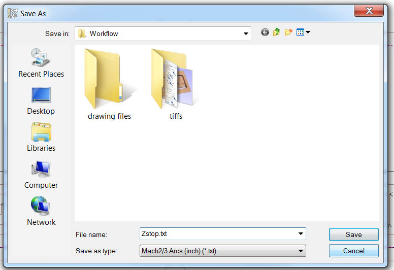
Step 7 - Export the Gcode
To convert the toolpaths to Gcode and save them to a file, I click the "Save Toolpath" icon shown below.

This will present the Save Toolpaths pane. I check each of the toolpaths. I check the "Output all visible toolpaths to one file" option.
I ensure the Mach2/3 Arcs (inch) Post Processor is chosen, and hit the "Save Toolpaths to File" button.

I give my Gcode file a name of "Zstop.txt". I hit the "Save" button.
Step 8 - Save Cut2D file
I also save a Cut2D project file. This way I can come back and modify the toolpaths later.
At this point all the CAD/CAM operations are complete. It's time to cut the part.
Step 9 - Load the stock
I will need a piece of 6" x 4" x 1/8" waster board for this project. Waster board is used to keep your bits from cutting your table surface. It is placed under your stock.
I place the 6" x 4" x 1/8" piece of waster board against the fences on my CNC machine. I then place my stock on top of the waster board. Here I am using a piece of 6" x 4" x 3/4" Poplar. Poplar is a good choice for the Z stop. Its firm enough to stop the Z axis, and soft enough to keep from damaging the bearings.
I clamp the stock in place. I like to use two clamps on each of the three exposed axes. Notice the third clamp in between the two clamps on the rear and side of the stock. These don't seem to be holding anything. They are in place to keep the waster board from sliding.

Step 10 - Reference the machine
Please note that at the time I created this work flow I had homing switches and Z probes. However I will proceed as though my machine does not have them.
I need to manually reference my machine to the fences at which my stock has been placed. I move the center of my router bit to the tip of the stock as shown below.
With my router bit moved into the reference position, I hit the large button labeled "REF ALL HOME." Hit each of the Zero buttons. The DRO's should display zero and the outline on the buttons should glow green. At this point, my CNC will call this place home. All movements will be based on this position being at x=0, y=0, z=0.

Step 11 - Load the Gcode file into Mach 3
In Mach 3, I load the Gcode file by selecting the "Load G-Code" option in the File menu, as shown below.

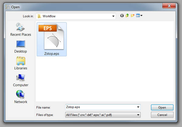
I click on the Zstop.txt file and hit the Open button.

Once the Gcode file has been loaded I see the instructions pane has been filled with Gcode instructions. I also see a graphical representation of the toolpaths in the display pane.


Note that if select the Tool Path tab, you will be presented with a screen (shown below) that provides more information about the Gcode you have loaded. The display pane is larger and the programs limits for each axis is displayed.

Step 12 - Machine the Part
Please note that at the time I created this work flow I have a relay controlled router. With a relay controlled router, Mach 3 will automatically turn the router on and off. I will proceed as though my router is controlled manually.
I am ready to machine the part. I set the speed of the router to about 14,000 RPMs. Using the jog controls I raise the router off the work surface and power on the router.
I turn on the router.
I have Mach 3 start running the Gcode by hitting the "Cycle Start" button.
The CNC machine then proceeds to cut the part. I keep an eye on the stock, making sure the clamps are holding it secure.
Note that most of my past part failures have been due to the stock moving.
Step 13 - Clean the Part
Depending on the material you are cutting you may have to clean the part. Poplar tends to leave little fibers attached to the upper edges. These are easily removed with a light sanding. You will also have to use a chisel to square up the outside edges. The cleaned up Z stop should look like the one shown below.

Step 14 - Paint the Part
You may want to paint your Z stop. You can use a latex or a oil based paint. The latex will dry faster. The oil based will give a better finish. Be sure to sand between coats.

Step 15 - Assemble the Z stop
Take two 5/16-18 x 1-1/2" hex bolts, and add a 5/16 lock washer, 5/16 washer. Insert the bolts into the two holes of the Z stop and then into the tapped holes in the bottom of the Z beam, as shown below.

Conclusion
Your Z stop is now installed.

See it in action here:
Fusion 360 Workflow
For those of you who want to try using Fusion 360 to make this part, here is a workflow sent in by a fellow KRMx02 builder.