
I was researching CNC drag knifes when I came across the Grunblau drag knife plans.
The plans are only $5, but they do require a lot of work to create the toolpaths needed to make the knife.
While I cant give you any derived drawings or gcode files, I can share the what I did to make the drag knife.
The Plans
Important - These are not my plans, they are the ones I used to build my knife. As such I do not sell these plans. This is a link to the individual who does.
You can pickup the plans here:
These are not really sold as plans, but more as geometry files, and they are just that. The files will require some editing in order to create your tool paths.
I started by importing the dxf files into Corel Draw as shown here.
I broke the files down into the following components:
Knife
Top Plate
Bottom Plate
Knife Clamp
While the top and bottom plate were straight forward enough, I did have to create some more geometry on the knife. I needed to to this in order to create the various pockets needed.
Each component was exported as a eps file so that I could import them into Vcarve Pro.
The bearings specified by the plans call for a bearing 1.125" in diameter with a .5" shaft hole. They are 5/16" thick.
The Stock
The stock I chose was 2.5" 6061 aluminum bar stock .375" thick.
It was cut into the following pieces:
2.5" x 2.5" x .375" (Bottom Plate)
2.5" x 2.5" x .375" (Top Plate)
3.75" x 2.5" x 3.75" (Knife)
Shown here is the knife stock mounted in my vise.
Before doing any milling I touched my tool to the left edge as shown here and set the X DRO to -.0625"
This needs to be set for each piece of stock.
I touched my bit to the front edge as shown here and set the Y DRO to -.0625.
This is the front jaw of the vise. And only needs to be set once for milling all the stock.
I used my probe to set the bit to the top of the stock.
In addition to the 3/8" stock I milled the knife clamp out of 1/16" 6061 aluminum stock.
Here I show a piece of 1" square aluminum tubing I used to mill the part.
The Tools

To mill all the parts, I decided to use an Onsrud 63-610 1/8" End Mill.
By using a 1/8" end mill, I was able to mill all the parts without changing tools.
Feeds and Speeds
RPM: 24,000
Feed: 40IPM Cut, 10IPM Finish
Plunge: 40IPM Cut, 10IPM Finish
DOC: .03 Cut, Full depth on Finish
Ramp: .5"
For a spindle, I am using a 2.2KW VFD controlled spindle.
I started a write up on VFD controlled spindles here:
This spindle has a range of 5000-24000 RPM and I will be running all the operations at 24000. If you are using a router that can not run at 24000 RPM, you will need to lower the feed rates.
I'm using an inexpensive mister as a blower for clearing chips. You can get one here:
I did a write up on converting it to blower here:
My lubricator is a work in progress. Currently its a mister that is gravity fed that will drop when the fluid valve is open.
It is connected to a solenoid that allows me to do a large burst of lubricator if needed.
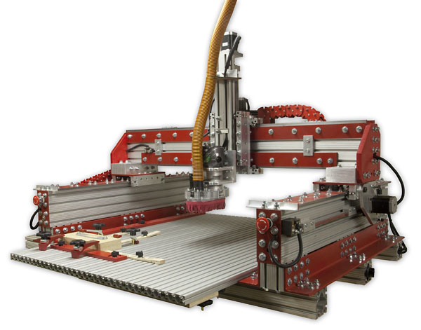
All the milling operations will be done on the KRMx02 CNC.
I will be pushing the maching operations more than is generally recommend so if you are using a machine that is not as ridged as the KRMx02, you will need to slow the feed rate down.
Bottom Plate
I imported the top plate dxf file into Vcarve Pro and created my tool paths. The plans dont really give any depths for the bearing pocket so I set my own.
I set the bearing pocket to .3". This leaves .075" of the stock to hold the bearing in place.
The three outside holes are sized for a tapping a 1/4-20 thread.
One important toolpath that I created was on the main profile cutout.
When cutting more than 1/4" with a small bit, clearing the chips becomes problematic. Even when blowing and lubricating.
To solve the problem, I created a channel about .18" deep. It is offset .1" from where the main profile cut will be done.
When the profile cut is made the channel will provide a way for the chips to be blown clear.
I did have to go back and remove another .002" from the pocket diameter. The bearing fits perfect.
I always test my bearing pocket before removing the part. This allows me to enlarge the pocket if needed.
Note that you need to remove the center waste first.
Here I have removed the part and cleaned up the tabs.
At this point I tap the three holes with a 1/4-20 tap.
Top Plate
The top plate is setup much the same as the bottom plate. It has the same outside profile to help clear the chips.
Here the bearing pocket is only .175" deep. There is an internal pocket that is .2" deep. This pocket is to keep the plate from rubbing against the bearing shaft hole.
The hole in the center is 1/2" and is used to press fit a piece of 1/2" tubing or rod.
The three outside holes are .29" in diameter to provide a little play when using 1/4" hardware to attach the two plates.
The bearing pocket is tested.
The shaft hole is tested.
The part.
Tabs removed and cleaned up.
The Blade Holder
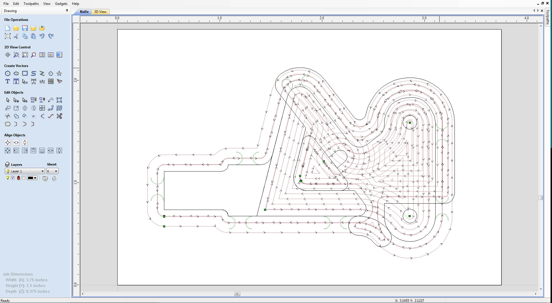
The blade holder was the most complicated part to create toolpaths for.
I used the provided Grunblau geometry, but had to do a lot of cutting and pasting in order to create the geometry needed for the various pockets.
Step 1
I start by milling the main pocket. It is milled to a depth of .175"
Step 2
I mill the two holes. They are designed with a diameter of .139. That said I gave them am offset of .003 and milled them very fast. This made the holes slightly over .125". This gave me enough meat to tap #6-32 threads.
Step 3
I mill the blade pocket. It is milled .2" deep.
Step 5
I cutout the small section shown here.
Step 6
I add the chip clearance profile .18" deep.
Step 7
To complete the knife holder, the main profile is cutout.
Blade Clamp
The blade clamps was machined from a piece of 1" square aluminum tubing stock. The stock is 1/16" thick which is perfect for the clamp.
Parts Prep
There are a few things you must do before assembling the drag knife.
The first thing is to attach the 1/2" tubing or rod to the top plate. I used a 1/2" Brass bushing for my shaft.
I did not want to rely on a press fit alone so I added some two part epoxy to mine.
Make sure the bottom of the shaft is flush with the innermost pocket.
In order to assemble the drag knife, you will need to round the corners ever so slightly. You will need a file for this.
Sneak up on the exact amount needed by removing small equal amounts from all corners.
Test the fit with each pass.
If you find that you have removed too much, you can use a chisel to add small dents to the corners, as shown here.
The little dents will tighten up the fit.
Assembly
Step 1
Insert one of the bearings into the bottom plate, then insert the knife holder into the bearing from the opposite side, as shown here.
Step 2
Add the other bearing to the assembly.
Step 3
Add the top plate and secure with three 1/4-20 x 1" bolts as shown here.
Step 4
Place the blade into position as shown here.
Step 5
Secure with the blade clamp and two #6-32 x 1/2" machine screws.
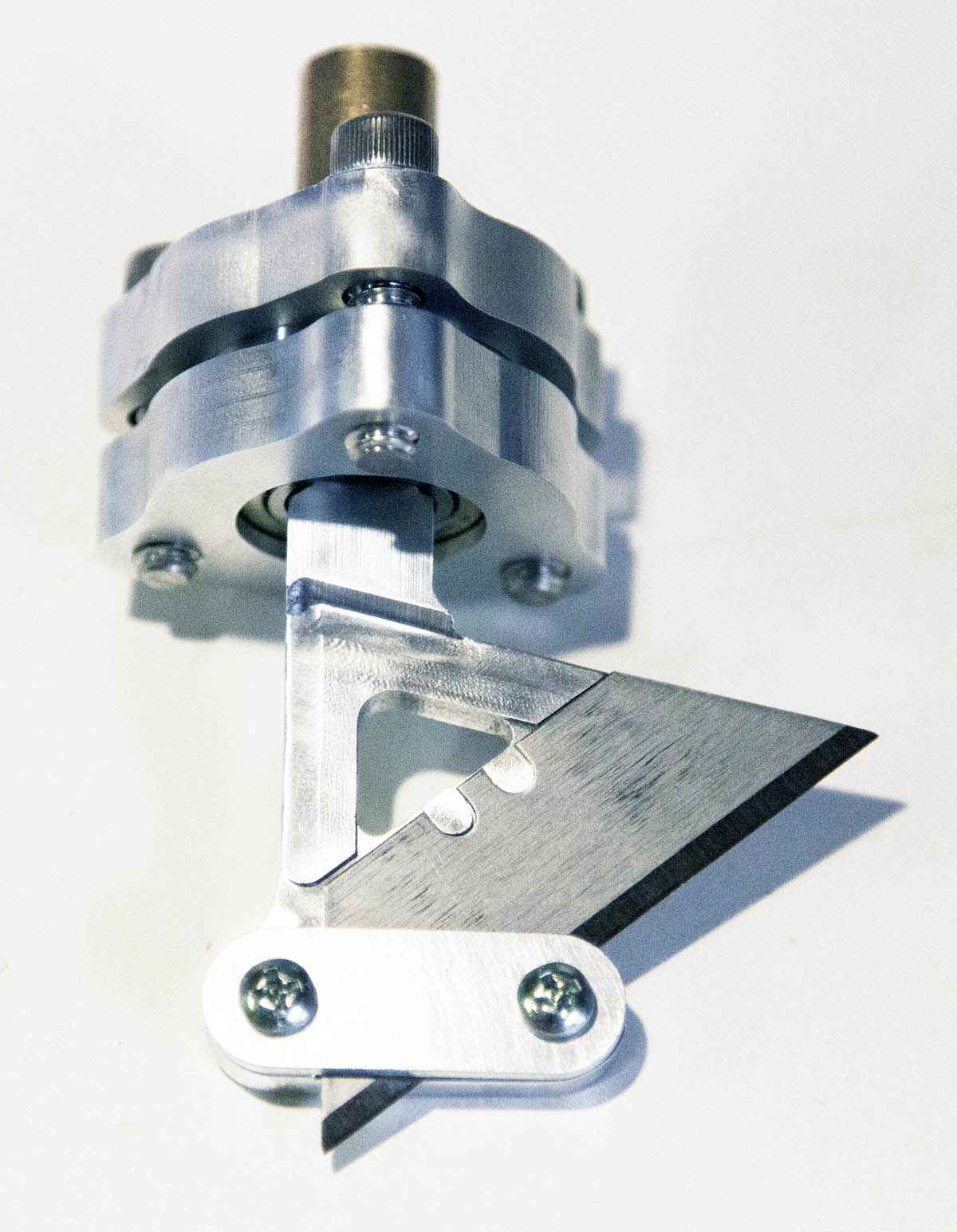
That's it. The drag knife has been assembled.
Conclusion
All that is left is to test the new drag knife. I will do just that in some upcoming projects.