

While I plan on writing a detailed book on routers and spindles, here is a simple mount to get you started.
Components you will need:
CNCRouterPart Mount (see text)
Router or spindle to match Mount
4, #10-24 x 1” Machine screws
4, #10-24 Hex nuts
4, #10 lock washers
Tools you will need:
Power drill or drill press
1/4” Drill bit
3/8” wrench
Philips screwdriver
3/16 Hex wrench
Router Centering Pin
Small square
The Philips screwdriver needs to be medium sized, with a reach of at least 5”. You will need to insert the screwdriver through the holes in the front of the mount in order to reach the screw heads.
The Mount
The mount I will be using is available from CNCRouterParts. They offer several form factors to accommodate just about any router or spindle and they all mount the same way.
You can get them here :
The actual one I will be using is for the Bosch 1617 router.
You can get that mount here:
Router here:
Important
When purchasing the mount, you do not need the base so select the “No Base Adapter or Hardware” option. This will bring the cost down to about $82.
Z Plate Modifications
In volume 2 of the CNC Construction Set series, you added two 1/4” holes to accommodate a pen holder used to tune the machine.
These two holes were located 1/2” from the bottom of the plate.
You will need to add two more 1/4” holes to the Z-plate.
The actual distance between the holes was not an arbitrary decision. They are 1” and 2-1/2” apart. This hole pattern will accommodate the following mounts:
CNCRP Spindle/Router Mounts
K2CNC Router Mounts
Velox Router Mounts
Here is the actual locations of the new holes.
You can lay them out from this drawing, or use this template.
When printing the template, you need to make sure the 7-1/4” and 2” dimensions are correct or the template will not work.
The holes can be drilled directly into the assembled Z-carriage.
Note that you will need to remove your Z-carriage assembly from the machine.
The finished Z-carriage assembly.
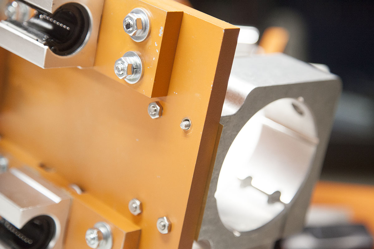
Attach The Router Mount
Use the four #10 machine screws and hex nuts to secure the router mount to the assembled Z-carriage.
Do not use the lock washers at this time. Snug the screws only.
Attach the Z-carriage to the machine.
Initial Adjustment
Place the worktable you created in volume 3 back on the machine.
Lower the Z-axis and place a square on the table against the mount as shown here.
Twist the mount as needed to square it to the table.
Tighten the screws enough that the mount does not easily move.
Drop the router into the mount. Secure by tightening both the hex head screws with a 3/16 hex wrench.
Note that if the router does not drop into the mount, you may need to loosen the hex head screws first.
Adjusting the Router
To make the following adjustments, you will need a router centering pin like the one shown here.
While it is possible to use an actual router bit, these are very cheap and much more accurate to use.
You can pick one up here:
Front to Rear Tuning
Lower or raise the Z-axis so that you can place the square against the front of the centering pin while resting on the table.
If it is not square, you will have to add a shim between the mount and the Z-plate to square it up.
You will have to loosen the mount enough to insert the shim.
Place the shim on the bottom if you need to move the bottom of the pin towards the square.
Place the shim on the top if you need to move the top of the pin towards the square.
You can pick up a set of shims here:
If you are having trouble dialing in the square, it is also possible to use the square against the inside of the mount as shown here. This will allow you to make adjustments without having to reinstall the router.
In addition it is also possible to add the shims while the Z-carriage is still installed on the machine, especially if your adding the shim to the top.
Note that the shim thickness should be about the sizes of the gap between the square and the pin.
Side to Side Tuning
Place the square against the side of the centering pin while resting on the table.
If the pin is not square, with some effort, you should be able to twist the mount until it is.
Once the router is square, loosen the two hex head screws on the mount and carefully remove the router.
Using a screwdriver and 3/8” wrench, tighten the four mounting screws.
Once tight, reinstall the router and tighten the hex head screws.
Recheck for square.
Final Tightening


In order to help secure the mounting screws, remove the nut from one of screws and add a lock washer.
Place the nut back on the screw and tighten.
Repeat with the next screw.
It is important to only loosen one of the nuts at a time to keep the mount from shifting.
Reinstall the Z-carriage and install the router.
Conclusion
Your router is now ready for use. For now, your router must be turned on and off manually, later I will show you how automate router control.